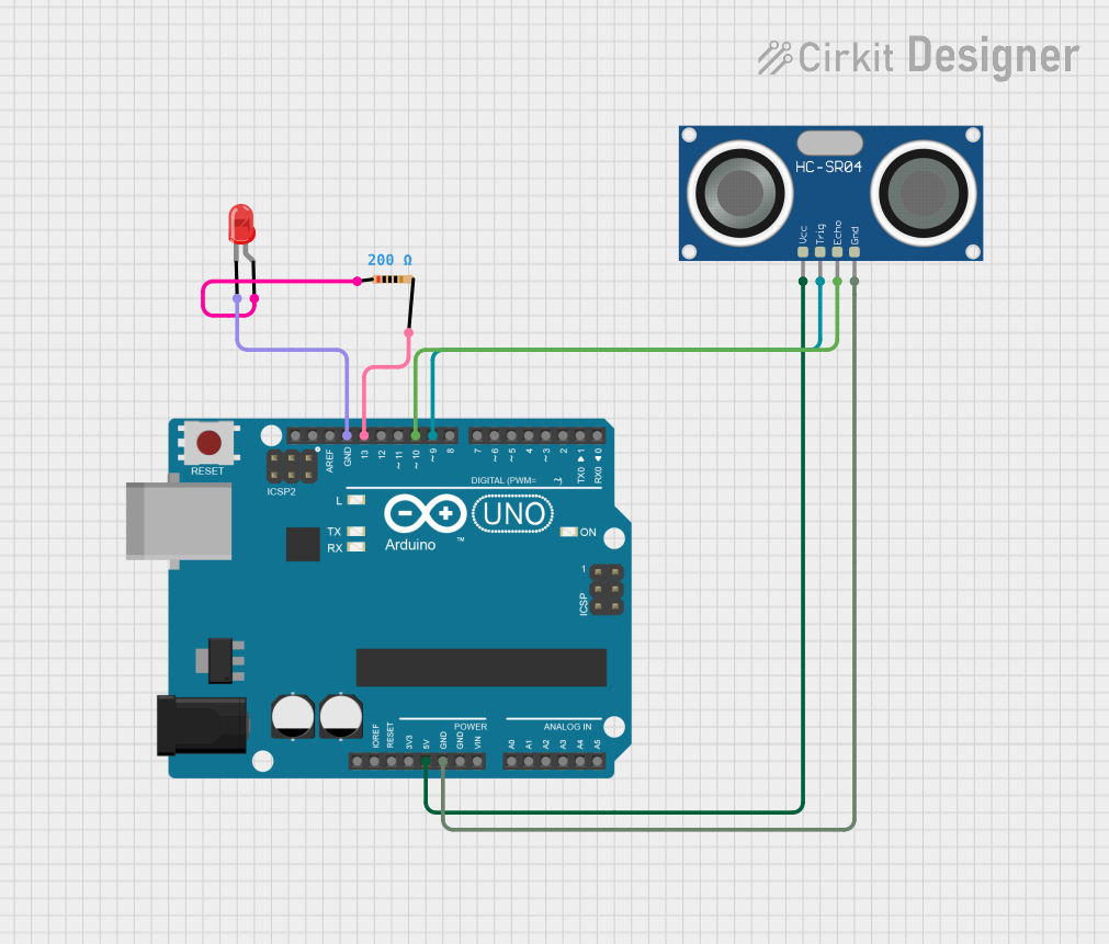
Arduino UNO Based Ultrasonic Distance Sensor with LED Indicator

Circuit Documentation
Summary of the Circuit
This circuit is designed to utilize an Arduino UNO microcontroller to interface with an HC-SR04 Ultrasonic Sensor and a red LED. The purpose of the circuit is to measure the distance of an object from the sensor and indicate the proximity of the object by blinking the LED at a rate proportional to the distance measured. The closer the object, the faster the LED blinks. The Arduino UNO is programmed to send a pulse to the ultrasonic sensor, which then emits an ultrasonic wave. When the wave hits an object, it is reflected back to the sensor. The Arduino calculates the distance based on the time it takes for the echo to return. If the measured distance is below a certain threshold, the LED is activated.
Component List
Arduino UNO
- Description: A microcontroller board based on the ATmega328P.
- Purpose: Acts as the central processing unit of the circuit, controlling the sensor and the LED.
HC-SR04 Ultrasonic Sensor
- Description: An ultrasonic distance sensor capable of measuring distances from 2cm to 400cm.
- Purpose: Measures the distance to an object by emitting ultrasonic waves and receiving the echo.
LED: Two Pin (red)
- Description: A basic red light-emitting diode.
- Purpose: Indicates the proximity of the object detected by the ultrasonic sensor.
Resistor (200 Ohms)
- Description: A passive two-terminal electrical component that implements electrical resistance.
- Purpose: Limits the current flowing through the LED to prevent damage.
Wiring Details
Arduino UNO
- 5V: Provides power to the HC-SR04 Ultrasonic Sensor.
- GND: Common ground for the circuit.
- D13: Connected to one end of the resistor, other end connected to the anode of the LED.
- D10: Receives the ECHO signal from the HC-SR04 Ultrasonic Sensor.
- D9: Sends the TRIG signal to the HC-SR04 Ultrasonic Sensor.
HC-SR04 Ultrasonic Sensor
- VCC: Connected to the 5V output from the Arduino UNO.
- GND: Connected to the ground (GND) on the Arduino UNO.
- TRIG: Connected to digital pin D9 on the Arduino UNO.
- ECHO: Connected to digital pin D10 on the Arduino UNO.
LED: Two Pin (red)
- Cathode: Connected to the ground (GND) on the Arduino UNO.
- Anode: Connected to one end of the resistor, other end connected to digital pin D13 on the Arduino UNO.
Resistor (200 Ohms)
- Pin1: Connected to the anode of the LED.
- Pin2: Connected to digital pin D13 on the Arduino UNO.
Documented Code
Arduino UNO Code
int trigpin=9; // Output pin for triggering ultrasonic pulse
int Echopin=10; // Input pin for receiving ultrasonic echo
int ledpin=13; // Output pin for controlling LED
int threshold_distance=30; // Distance threshold for LED activation (in cm)
long duration;
int distance;

void setup() {
    pinMode(trigpin, OUTPUT);
    pinMode(Echopin, INPUT);
    pinMode(ledpin, OUTPUT);
    Serial.begin(9600); // Start serial communication at 9600 bps
}

void loop() {
    // Trigger ultrasonic pulse
    digitalWrite(trigpin, LOW);
    delayMicroseconds(2);
    digitalWrite(trigpin, HIGH);
    delayMicroseconds(10);
    digitalWrite(trigpin, LOW);

    // Read echo pulse
    duration = pulseIn(Echopin, HIGH);

    // Calculate distance from duration
    distance = (0.034 * duration) / 2;
    Serial.print(distance);
    Serial.println("cm");

    // Blink LED based on distance
    if(distance < threshold_distance) {
        int ledblink = map(distance, 0, threshold_distance, 100, 500);
        digitalWrite(ledpin, HIGH);
        delay(ledblink);
        digitalWrite(ledpin, LOW);
        delay(ledblink);
    } else {
        digitalWrite(ledpin, LOW);
    }
}
This code is designed to run on the Arduino UNO microcontroller. It initializes the necessary pins, performs distance measurements using the HC-SR04 Ultrasonic Sensor, and blinks the LED at a rate inversely proportional to the measured distance. The serial communication is used for debugging purposes to output the distance measurements to the serial monitor.