
ESP32-CAM Controlled Solenoid Lock with BC547 Transistor Switching
View and Edit Project In Cirkit Designer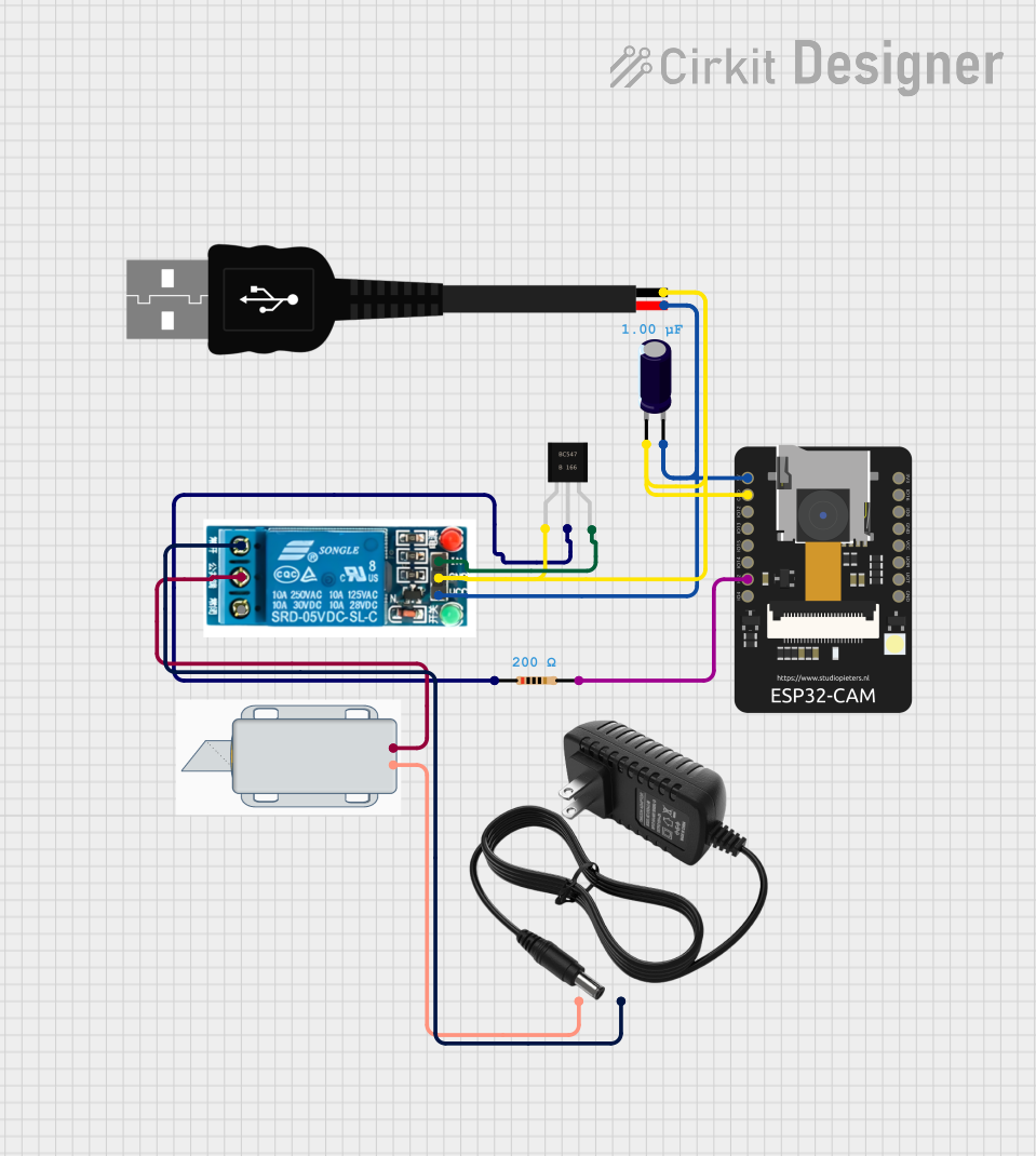
Circuit Documentation
Summary
The circuit in question appears to be designed for controlling a 12V solenoid lock using an ESP32-CAM microcontroller. The ESP32-CAM is responsible for the logic control and interfaces with a 5V relay to drive the solenoid lock. A BC547 transistor is used to interface between the ESP32-CAM and the relay, with a resistor providing the necessary biasing for the transistor. Power management is handled by a USB male 2-pin connection for the ESP32-CAM and a 12V power supply for the solenoid lock. An electrolytic capacitor is included, likely for power supply decoupling to reduce voltage spikes and noise.
Component List
Resistor
- Description: A resistor with a resistance value of 200 Ohms.
- Purpose: To provide biasing for the BC547 transistor.
BC547 Transistor
- Description: A general-purpose NPN transistor.
- Purpose: To act as a switch for controlling the relay with the ESP32-CAM.
ESP32-CAM
- Description: A microcontroller with Wi-Fi and camera capabilities.
- Purpose: To serve as the main control unit for the circuit, interfacing with the relay and potentially providing image capture capabilities.
5V Relay
- Description: An electromechanical switch that can be controlled with 5V logic signals.
- Purpose: To switch the 12V power supply to the solenoid lock.
USB Male 2-Pin Connection
- Description: A USB connector for power input.
- Purpose: To provide 5V power to the ESP32-CAM and relay.
12V Solenoid Lock
- Description: An electrically-controlled lock that operates on 12V.
- Purpose: To act as the locking mechanism controlled by the circuit.
12V Power Supply
- Description: A power source that provides 12V.
- Purpose: To power the solenoid lock.
Electrolytic Capacitor
- Description: A capacitor with a capacitance value of 1 microfarad (0.000001 Farads).
- Purpose: To provide decoupling for the power supply, reducing noise and voltage spikes.
Wiring Details
Resistor
- Connections:
- One end connected to the base of the BC547 transistor.
- The other end connected to IO2 of the ESP32-CAM.
BC547 Transistor
- Connections:
- Base connected to a 200 Ohm resistor.
- Collector connected to the ground net, which includes the GND pin of the ESP32-CAM, the negative terminal of the USB connection, and the GND pin of the 5V relay.
- Emitter connected to the "In" pin of the 5V relay.
ESP32-CAM
- Connections:
- IO2 connected to a 200 Ohm resistor.
- 5V connected to the positive terminal of the USB connection and the VCC pin of the 5V relay.
- GND connected to the ground net, which includes the negative terminal of the USB connection, the collector of the BC547 transistor, and the GND pin of the 5V relay.
5V Relay
- Connections:
- Normally Open (NO) connected to the negative terminal of the 12V power supply.
- Common terminal connected to the positive terminal of the 12V solenoid lock.
- Normally Closed (NC) not connected in this circuit.
- In connected to the emitter of the BC547 transistor.
- GND connected to the ground net.
- VCC connected to the positive terminal of the USB connection.
USB Male 2-Pin Connection
- Connections:
- Positive (+) connected to the 5V pin of the ESP32-CAM and the VCC pin of the 5V relay.
- Negative (-) connected to the ground net.
12V Solenoid Lock
- Connections:
- Positive (+) connected to the common terminal of the 5V relay.
- Negative (-) connected to the positive terminal of the 12V power supply.
12V Power Supply
- Connections:
- Positive (+) connected to the negative terminal of the 12V solenoid lock.
- Negative (-) connected to the Normally Open (NO) pin of the 5V relay.
Electrolytic Capacitor
- Connections:
- Positive (+) connected to the 5V pin of the ESP32-CAM and the positive terminal of the USB connection.
- Negative (-) connected to the ground net.
Documented Code
No code has been provided for the microcontroller in this circuit. For the ESP32-CAM to function as intended, embedded code would be required to initialize the GPIO pins, handle Wi-Fi connectivity, capture images (if used for that purpose), and control the relay based on the desired logic.