Arduino-Controlled Stepper and DC Motor Winding Machine with LCD Interface and IR Sensing
Circuit Documentation
Summary
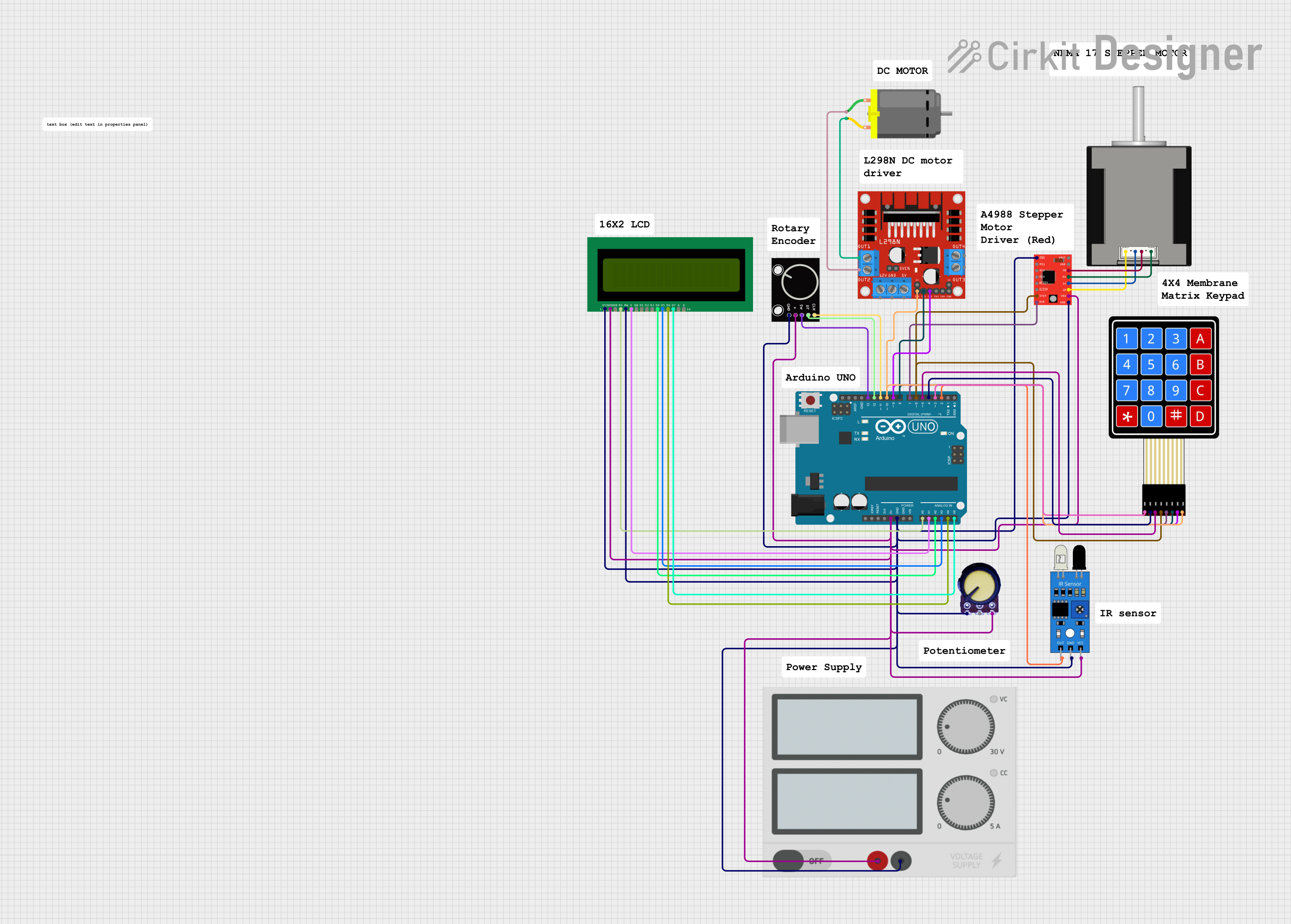
This circuit is designed to control a stepper motor and a DC motor using an Arduino UNO microcontroller. It includes a user interface with a 16x2 LCD display and a 4x4 membrane matrix keypad for input. The circuit also features a rotary encoder for additional input, an IR sensor for detecting motor rotations, and a potentiometer for variable input. The A4988 stepper motor driver is used to drive a Nema 17 stepper motor, and the L298N motor driver controls the DC motor. Power is supplied to the circuit components through a common power supply.
Component List
A4988 Stepper Motor Driver (Red)
- A driver module for controlling stepper motors, particularly used for precision control of a Nema 17 stepper motor in this circuit.
DC Motor
- A standard DC motor controlled by the L298N motor driver, used for applications requiring rotational motion.
Rotary Encoder
- An input device that provides rotational position feedback and can also be used as a push-button.
Arduino UNO
- A microcontroller board based on the ATmega328P, used as the central controller for the circuit.
Potentiometer
- A three-terminal resistor with an adjustable voltage divider, often used for adjusting electrical parameters like volume or position.
IR Sensor
- An infrared sensor used for detecting proximity or measuring the rotation of the DC motor.
Nema 17 Stepper Motor (42-STH48)
- A stepper motor used for precise control of position, speed, and acceleration.
16x2 LCD
- A liquid crystal display capable of displaying 16 characters per line across 2 lines, used for user interface feedback.
4x4 Membrane Matrix Keypad
- A keypad with 16 buttons arranged in a 4x4 matrix, used for user input.
Power Supply
- Provides the necessary electrical power to the circuit components.
L298N DC Motor Driver
- A dual H-bridge motor driver capable of driving a pair of DC motors or a single bipolar stepper motor.
Wiring Details
A4988 Stepper Motor Driver (Red)
- ENABLE, MS1, MS2, MS3, RESET, SLEEP: Not connected
- STEP: Connected to Arduino UNO D6
- DIR: Connected to Arduino UNO D7
- VMOT: Not connected
- GND: Common ground
- 2B: Connected to Nema 17 B2 (Red)
- 2A: Connected to Nema 17 B1 (Blue)
- 1A: Connected to Nema 17 A1 (Green)
- 1B: Connected to Nema 17 A2 (Black)
- VDD: Connected to 5V power rail
DC Motor
- Pin 1: Connected to L298N OUT2
- Pin 2: Connected to L298N OUT1
Rotary Encoder
- GND: Common ground
- +: Connected to 5V power rail
- SW: Connected to Arduino UNO D13
- DT: Connected to Arduino UNO D12
- CLK: Connected to Arduino UNO D11
Arduino UNO
- 5V: Connected to 5V power rail
- GND: Common ground
- A0-A5: Connected to 16x2 LCD RS, E, D4, D5, D6, D7 respectively
- D2-D10: Connected to various components for control signals
Potentiometer
- GND: Common ground
- Output: Not connected
- VCC: Connected to 5V power rail
IR Sensor
- Out: Connected to Arduino UNO D2
- Gnd: Common ground
- Vcc: Connected to 5V power rail
Nema 17 Stepper Motor (42-STH48)
- A2 (Black): Connected to A4988 1B
- A1 (Green): Connected to A4988 1A
- B2 (Red): Connected to A4988 2B
- B1 (Blue): Connected to A4988 2A
16x2 LCD
- VSS: Common ground
- VDD: Connected to 5V power rail
- V0: Not connected
- RS: Connected to Arduino UNO A0
- RW: Common ground
- E: Connected to Arduino UNO A1
- D0-D3: Not connected
- D4: Connected to Arduino UNO A2
- D5: Connected to Arduino UNO A3
- D6: Connected to Arduino UNO A4
- D7: Connected to Arduino UNO A5
- A, K: Not connected
4x4 Membrane Matrix Keypad
- R1-R4: Connected to Arduino UNO D3-D6 respectively
- C1-C4: Connected to Arduino UNO D7, D8, D9, D10 respectively
Power Supply
- +: Connected to 5V power rail
- -: Common ground
L298N DC Motor Driver
- OUT1, OUT2: Connected to DC Motor
- 12V, 5V, 5V-ENA-JMP-I, 5V-ENA-JMP-O, +5V-J1, +5V-J2, OUT3, OUT4, ENB: Not connected
- GND: Common ground
- ENA: Connected to Arduino UNO D10
- IN1: Connected to Arduino UNO D8
- IN2: Connected to Arduino UNO D9
Documented Code
#include <LiquidCrystal.h>
#include <Keypad.h>

// LCD pins
LiquidCrystal lcd(A0, A1, A2, A3, A4, A5);

// Keypad setup
const byte ROWS = 4;
const byte COLS = 4;
char keys[ROWS][COLS] = {
  {'1','2','3','A'},
  {'4','5','6','B'},
  {'7','8','9','C'},
  {'*','0','#','D'}
};
byte rowPins[ROWS] = {3, 4, 5, 6};
byte colPins[COLS] = {7, 8, 9, 10};
Keypad keypad = Keypad(makeKeymap(keys), rowPins, colPins, ROWS, COLS);

// Motor pins
const int stepPin = 6;
const int dirPin = 7;
const int dcMotorPin1 = 8;
const int dcMotorPin2 = 9;
const int dcMotorEnable = 10;
const int irSensorPin = 2;

int turns = 0;
int targetTurns = 0;

void setup() {
  lcd.begin(16, 2);
  lcd.print("Enter Turns:");

  pinMode(stepPin, OUTPUT);
  pinMode(dirPin, OUTPUT);
  pinMode(dcMotorPin1, OUTPUT);
  pinMode(dcMotorPin2, OUTPUT);
  pinMode(dcMotorEnable, OUTPUT);
  pinMode(irSensorPin, INPUT);
}

void loop() {
  char key = keypad.getKey();
  if (key) {
    if (key >= '0' && key <= '9') {
      targetTurns = targetTurns * 10 + (key - '0');
      lcd.setCursor(0, 1);
      lcd.print(targetTurns);
    } else if (key == '#') {
      lcd.clear();
      lcd.print("Winding...");
      startWinding();
      lcd.clear();
      lcd.print("Done!");
    }
  }
}

void startWinding() {
  turns = 0;
  attachInterrupt(digitalPinToInterrupt(irSensorPin), countTurns, RISING);

  digitalWrite(dcMotorEnable, HIGH);
  digitalWrite(dcMotorPin1, HIGH);
  digitalWrite(dcMotorPin2, LOW);

  while (turns < targetTurns) {
    digitalWrite(stepPin, HIGH);
    delayMicroseconds(800);
    digitalWrite(stepPin, LOW);
    delayMicroseconds(800);
  }

  digitalWrite(dcMotorEnable, LOW);
  detachInterrupt(digitalPinToInterrupt(irSensorPin));
}

void countTurns() {
  turns++;
}
This code is designed to run on the Arduino UNO microcontroller. It initializes the LCD and keypad, sets up the motor control pins, and defines the main loop and functions for the user interface and motor control. The startWinding function is responsible for controlling the stepper motor based on the number of turns entered by the user through the keypad. The IR sensor is used to count the number of turns made by the motor.