Cirkit Designer
Your all-in-one circuit design IDE
Home /
Project Documentation
Arduino UNO Controlled Water Quality Monitoring System with Relay-Operated Pump
Circuit Documentation
Summary
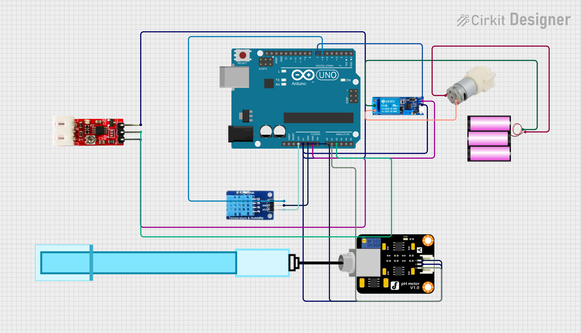
This circuit is designed to interface various sensors and a relay module with an Arduino UNO microcontroller. The sensors include a DHT11 temperature and humidity sensor, a PH Meter for measuring the acidity of a solution, and a Turbidity Module for assessing water clarity. A relay module is used to control a 12V water pump, powered by a 12V battery. The Arduino UNO serves as the central processing unit, reading sensor data and controlling the relay based on programmed logic.
Component List
Arduino UNO
- Microcontroller board based on the ATmega328P
- It has 14 digital input/output pins, 6 analog inputs, a 16 MHz quartz crystal, a USB connection, a power jack, an ICSP header, and a reset button.
Relay Module 5V-30V
- An electrically operated switch that allows you to turn on or off a circuit using voltage and/or current much higher than a microcontroller can handle.
- It has a trigger pin, common contact, normally open, and normally closed contact.
Water Pump 12V
- A pump that operates on 12V DC, used for moving water or other fluids.
Battery 12V
- A 12V DC power source used to power the water pump.
DHT11
- A basic, ultra low-cost digital temperature and humidity sensor.
- It uses a capacitive humidity sensor and a thermistor to measure the surrounding air and outputs a digital signal on the data pin.
PH Meter
- An electronic device used for measuring the pH (acidity or alkalinity) of a liquid.
Turbidity Module
- A sensor for measuring water clarity, with an output that can be read by a microcontroller.
Wiring Details
Arduino UNO
3.3Vconnected to DHT11 VCC5Vconnected to Turbidity Module VCC, PH Meter VCC, and Relay Module V+GNDconnected to DHT11 GND, PH Meter GND, Turbidity Module GND, and Relay Module V-A1connected to PH Meter SignalA2connected to Turbidity Module OUTD6connected to DHT11 DATAD7connected to Relay Module trigger
Relay Module 5V-30V
V+connected to Arduino UNO 5VV-connected to Arduino UNO GNDtriggerconnected to Arduino UNO D7common contactconnected to Battery 12V +normally closedconnected to Water Pump 12V +
Water Pump 12V
+connected to Relay Module normally closed-connected to Battery 12V -
Battery 12V
+connected to Relay Module common contact-connected to Water Pump 12V -
DHT11
VCCconnected to Arduino UNO 3.3VGNDconnected to Arduino UNO GNDDATAconnected to Arduino UNO D6
PH Meter
Signalconnected to Arduino UNO A1VCCconnected to Arduino UNO 5VGNDconnected to Arduino UNO GND
Turbidity Module
OUTconnected to Arduino UNO A2VCCconnected to Arduino UNO 5VGNDconnected to Arduino UNO GND
Documented Code
Arduino UNO Code (sketch.ino)
void setup() {
  // put your setup code here, to run once:

}

void loop() {
  // put your main code here, to run repeatedly:

}
Additional Documentation (documentation.txt)
No additional documentation provided in the code input.