
Circuit Documentation
Summary
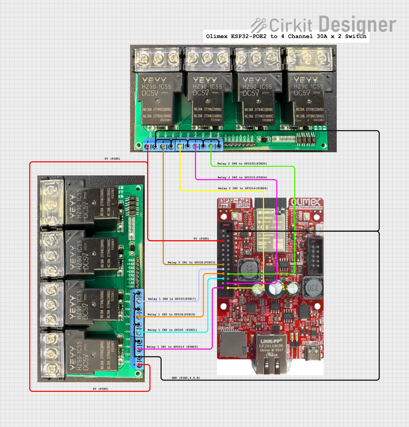
This document provides a detailed overview of a circuit that includes an ESP32-POE2 microcontroller and two 4 Channel 30A 5V Relays. The ESP32-POE2 is used to control the relays, which can be used to switch high-power devices. The circuit is designed to be powered by a 5V power supply.
Component List
ESP32-POE2
- Description: A microcontroller with integrated Wi-Fi and Bluetooth, designed for IoT applications.
- Pins:
- 12/24V Selectable
- 5VP
- 5V
- 3.3V
- EN
- GPIO0
- GPIO1/U0TXD
- GPIO2/HS2_DATA0
- GPIO3/U0RXD
- GPIO4/U1TXD
- GPIO5/SPI_CS
- GPIO12/PHY_PWR (MTDI)
- GPIO13/12C-SDA (MTCK)
- GND
- GPI39
- GPI36/U1RXD
- GPI35
- GPI34/BUT1
- GPIO33
- GPIO32
- GPIO16/I2C-SCL
- GPIO15/HS2_CMD(MTDO)
- GPIO14/HS2_CLK(MTMS)
- GPIO13/I2C-SDA (MTCK)
4 Channel 30A 5V Relay (2 units)
- Description: A relay module capable of switching high-power devices, controlled by a 5V signal.
- Pins:
- 5V
- GND
- IN1+
- IN1-
- IN2+
- IN2-
- IN3+
- IN3-
- IN4+
- IN4-
Wiring Details
ESP32-POE2
- 5V: Connected to the 5V pin of both 4 Channel 30A 5V Relays.
- GPIO2/HS2_DATA0: Connected to IN1+ of the first 4 Channel 30A 5V Relay.
- GPIO3/U0RXD: Connected to IN4+ of the second 4 Channel 30A 5V Relay.
- GPIO4/U1TXD: Connected to IN3+ of the second 4 Channel 30A 5V Relay.
- GPIO5/SPI_CS: Connected to IN2+ of the second 4 Channel 30A 5V Relay.
- GPIO13/12C-SDA (MTCK): Connected to IN1+ of the second 4 Channel 30A 5V Relay.
- GND: Connected to the GND pin of both 4 Channel 30A 5V Relays.
4 Channel 30A 5V Relay (First Unit)
- 5V: Connected to the 5V pin of the ESP32-POE2.
- GND: Connected to the GND pin of the ESP32-POE2.
- IN1+: Connected to GPIO2/HS2_DATA0 of the ESP32-POE2.
- IN1-: Connected to GND.
- IN2+: Connected to GPIO14/HS2_CLK(MTMS) of the ESP32-POE2.
- IN2-: Connected to GND.
- IN3+: Connected to GPIO15/HS2_CMD(MTDO) of the ESP32-POE2.
- IN3-: Connected to GND.
- IN4+: Connected to GPIO32 of the ESP32-POE2.
- IN4-: Connected to GND.
4 Channel 30A 5V Relay (Second Unit)
- 5V: Connected to the 5V pin of the ESP32-POE2.
- GND: Connected to the GND pin of the ESP32-POE2.
- IN1+: Connected to GPIO13/12C-SDA (MTCK) of the ESP32-POE2.
- IN1-: Connected to GND.
- IN2+: Connected to GPIO5/SPI_CS of the ESP32-POE2.
- IN2-: Connected to GND.
- IN3+: Connected to GPIO4/U1TXD of the ESP32-POE2.
- IN3-: Connected to GND.
- IN4+: Connected to GPIO3/U0RXD of the ESP32-POE2.
- IN4-: Connected to GND.
Code
No code is provided for this circuit.
This document provides a comprehensive overview of the circuit, including a summary, component list, wiring details, and code documentation. The ESP32-POE2 microcontroller is used to control two 4 Channel 30A 5V Relays, allowing for the switching of high-power devices.