
Solar-Powered Motion-Activated LED Circuit Documentation
Summary
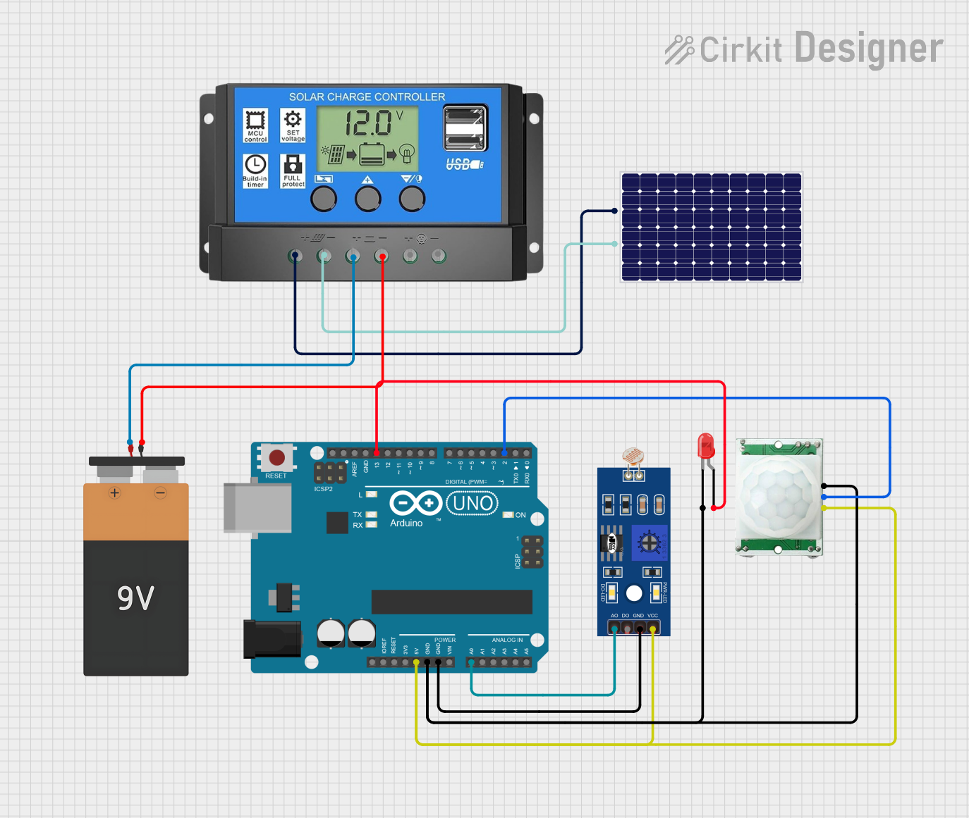
This circuit is designed to harness solar energy to charge a 9V battery, which in turn powers an Arduino UNO microcontroller along with a Light-Dependent Resistor (LDR), a Passive Infrared (PIR) motion sensor, and an LED. The Arduino UNO reads the ambient light level through the LDR and detects motion via the PIR sensor. When the environment is dark and motion is detected, the LED is turned on, indicating the presence of an individual or moving object.
Component List
Solar Panel
- Description: A photovoltaic module that converts sunlight into electrical energy.
- Pins:
+,-
Solar Charge Controller
- Description: Regulates the voltage and current coming from the solar panels to charge the battery and prevent overcharging.
- Pins:
Solar Cell +,Solar Cell -,Battery +,Battery -,Load +,Load -
Battery 9V
- Description: Provides energy storage for the circuit to operate when solar power is insufficient.
- Pins:
VCC,GND
LDR (Light-Dependent Resistor)
- Description: A sensor that changes resistance based on the ambient light level.
- Pins:
A0,D0,GND,VCC
PIR/Motion Sensor
- Description: Detects motion by measuring changes in the infrared levels emitted by surrounding objects.
- Pins:
GND,OUTPUT,VCC
LED: Two Pin (red)
- Description: A red light-emitting diode used as an indicator.
- Pins:
cathode,anode
Arduino UNO
- Description: A microcontroller board based on the ATmega328P, used for controlling the sensors and LED.
- Pins:
UNUSED,IOREF,Reset,3.3V,5V,GND,Vin,A0toA5,SCL,SDA,AREF,D13toD0
Wiring Details
Solar Panel
+connected to Solar Charge ControllerSolar Cell +-connected to Solar Charge ControllerSolar Cell -
Solar Charge Controller
Battery +connected to Battery 9VVCCBattery -connected to Battery 9VGND
Battery 9V
VCCconnected to Solar Charge ControllerBattery +GNDconnected to Solar Charge ControllerBattery -
LDR
VCCconnected to Arduino UNO5VGNDconnected to Arduino UNOGNDA0connected to Arduino UNOA0
PIR/Motion Sensor
VCCconnected to Arduino UNO5VGNDconnected to Arduino UNOGNDOUTPUTconnected to Arduino UNOD2
LED: Two Pin (red)
anodeconnected to Arduino UNOD13cathodeconnected to Arduino UNOGND
Arduino UNO
5Vconnected to LDRVCCand PIR/Motion SensorVCCGNDconnected to LEDcathode, PIR/Motion SensorGND, and LDRGNDA0connected to LDRA0D13connected to LEDanodeD2connected to PIR/Motion SensorOUTPUT
Documented Code
// sketch.ino
const int ldrPin = A0; // LDR connected to A0
const int pirPin = 2;  // PIR sensor connected to D2
const int ledPin = 13; // LED connected to D13

void setup() {
  pinMode(ldrPin, INPUT); // Set LDR pin as input
  pinMode(pirPin, INPUT); // Set PIR pin as input
  pinMode(ledPin, OUTPUT); // Set LED pin as output
  Serial.begin(9600); // Initialize serial communication
}

void loop() {
  int ldrValue = analogRead(ldrPin); // Read LDR value
  int pirValue = digitalRead(pirPin); // Read PIR value

  Serial.print("LDR Value: ");
  Serial.println(ldrValue);
  Serial.print("PIR Value: ");
  Serial.println(pirValue);

  // Check if it is dark and motion is detected
  if (ldrValue < 500 && pirValue == HIGH) {
    digitalWrite(ledPin, HIGH); // Turn on LED
  } else {
    digitalWrite(ledPin, LOW); // Turn off LED
  }

  delay(1000); // Wait for 1 second
}
This code is designed to be uploaded to the Arduino UNO microcontroller. It initializes the LDR and PIR sensor as inputs and the LED as an output. The loop function continuously reads the values from the LDR and PIR sensor, printing them to the serial monitor. If the LDR value indicates low light (value below 500) and the PIR sensor detects motion (value is HIGH), the LED is turned on. Otherwise, the LED is turned off. The system pauses for 1 second between each loop iteration.