
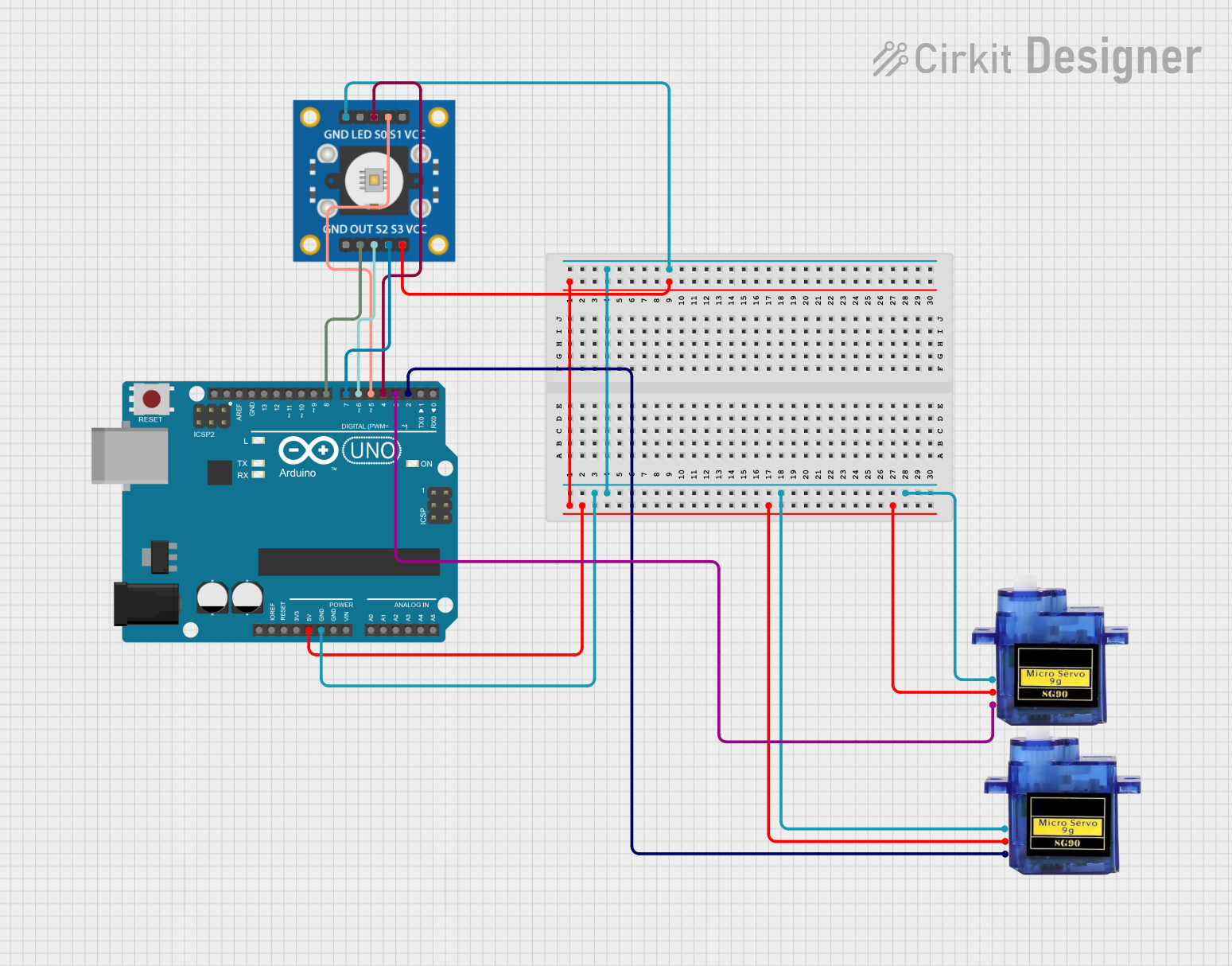
Circuit Documentation
Summary of the Circuit
This circuit integrates an Arduino UNO microcontroller with a TCS3200 color sensor and two Micro Servo 9G motors. The Arduino UNO serves as the central processing unit, controlling the servos and reading data from the color sensor. The TCS3200 color sensor is used to detect the color of objects, and its output is fed into the Arduino for processing. The Micro Servo 9G motors are controlled by the Arduino to perform actions based on the sensor input. The circuit is powered by the 5V output from the Arduino, which is distributed to the servos and the color sensor. Ground connections are shared among all components to complete the circuit.
Component List
Arduino UNO
- Description: A microcontroller board based on the ATmega328P.
- Pins: UNUSED, IOREF, Reset, 3.3V, 5V, GND, Vin, A0-A5, SCL, SDA, AREF, D0-D13
TCS3200 Color Sensor
- Description: A color sensor that can detect and measure a wide range of colors.
- Pins: GND, OUT, S0-S3, VCC, LED
Micro Servo 9G (2 units)
- Description: A small and lightweight servo motor suitable for small-scale projects.
- Pins: GND, +5V, PWM
Wiring Details
Arduino UNO
- 5V: Connected to the +5V pins of both Micro Servo 9G motors and the VCC pin of the TCS3200 color sensor.
- GND: Connected to the GND pins of both Micro Servo 9G motors and the GND pin of the TCS3200 color sensor.
- D2: Connected to the PWM pin of one Micro Servo 9G.
- D3: Connected to the PWM pin of the other Micro Servo 9G.
- D4: Connected to the S0 pin of the TCS3200 color sensor.
- D5: Connected to the S1 pin of the TCS3200 color sensor.
- D6: Connected to the S2 pin of the TCS3200 color sensor.
- D7: Connected to the S3 pin of the TCS3200 color sensor.
- D8: Connected to the OUT pin of the TCS3200 color sensor.
TCS3200 Color Sensor
- VCC: Connected to the 5V pin of the Arduino UNO.
- GND: Connected to the GND pin of the Arduino UNO.
- OUT: Connected to the D8 pin of the Arduino UNO.
- S0: Connected to the D4 pin of the Arduino UNO.
- S1: Connected to the D5 pin of the Arduino UNO.
- S2: Connected to the D6 pin of the Arduino UNO.
- S3: Connected to the D7 pin of the Arduino UNO.
Micro Servo 9G (First Unit)
- +5V: Connected to the 5V pin of the Arduino UNO.
- GND: Connected to the GND pin of the Arduino UNO.
- PWM: Connected to the D2 pin of the Arduino UNO.
Micro Servo 9G (Second Unit)
- +5V: Connected to the 5V pin of the Arduino UNO.
- GND: Connected to the GND pin of the Arduino UNO.
- PWM: Connected to the D3 pin of the Arduino UNO.
Documented Code
Arduino UNO Code (sketch.ino)
void setup() {
  // put your setup code here, to run once:

}

void loop() {
  // put your main code here, to run repeatedly:

}
Additional Notes
- The provided code is a template and does not contain any functional code for controlling the servos or reading from the color sensor. The user is expected to fill in the setup and loop functions with the necessary code to initialize the pins and implement the desired functionality.
- The
documentation.txtfile is empty and can be used to add additional notes or explanations about the code and circuit operation.