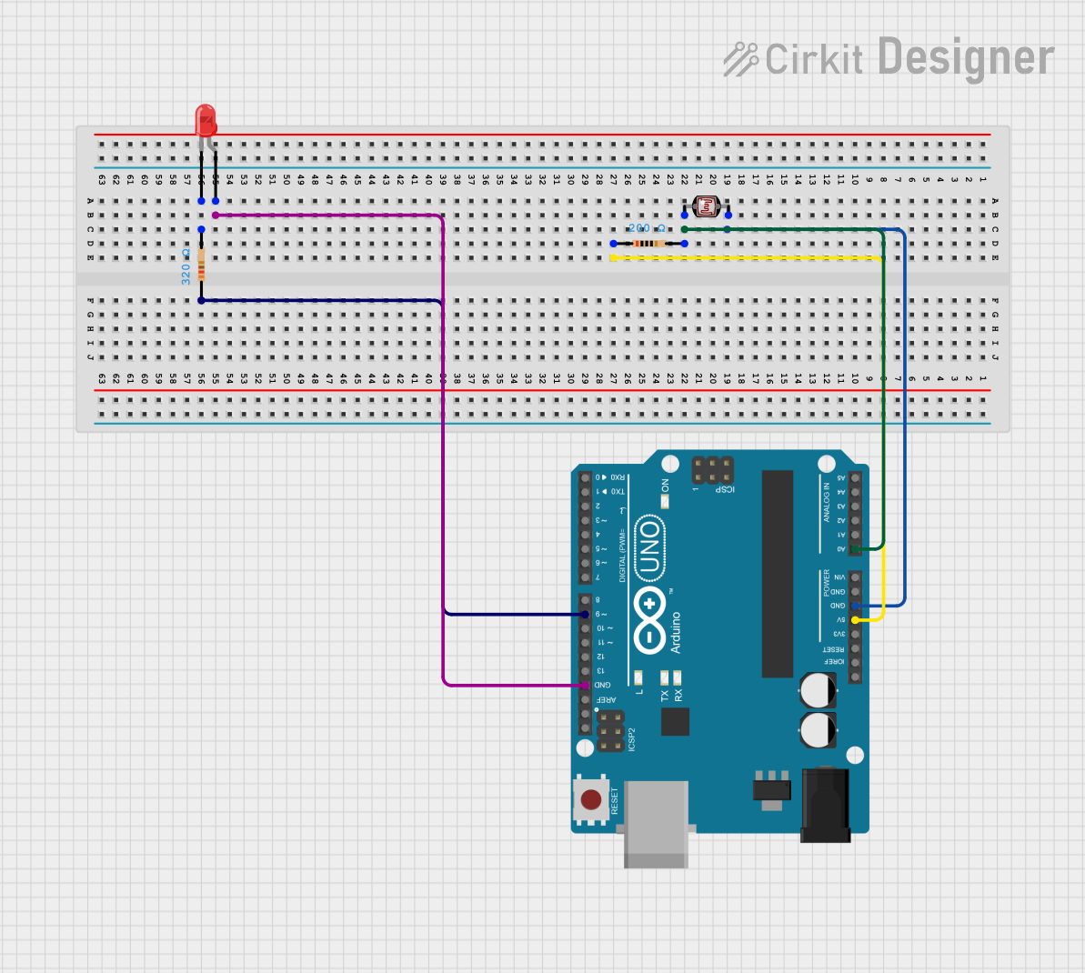
Arduino-Controlled Light Sensor with LED Indicator

Circuit Documentation
Summary of the Circuit
This circuit is designed to read the ambient light level using a photocell (Light Dependent Resistor, LDR) and control an LED based on the light intensity. The Arduino UNO microcontroller is used to read the analog voltage across the LDR, which changes with light intensity, and to drive the LED. The LED lights up when the voltage from the LDR is above a certain threshold, indicating low light conditions.
Component List
LED: Two Pin (red)
- Description: A red LED that lights up when current flows from the anode to the cathode.
- Purpose: To visually indicate the light level as detected by the LDR.
Resistor (320 Ohms)
- Description: A resistor with a resistance of 320 Ohms.
- Purpose: To limit the current flowing through the LDR to protect it and the Arduino from excessive current.
Arduino UNO
- Description: A microcontroller board based on the ATmega328P.
- Purpose: To process the analog signal from the LDR and control the LED accordingly.
Photocell (LDR)
- Description: A light-dependent resistor whose resistance changes with light intensity.
- Purpose: To sense the ambient light level.
Resistor (200 Ohms)
- Description: A resistor with a resistance of 200 Ohms.
- Purpose: To limit the current flowing through the LED to protect it from excessive current.
Wiring Details
LED: Two Pin (red)
- Anode: Connected to the ground (GND) of the Arduino UNO.
- Cathode: Connected to a 200 Ohm resistor, which is then connected to pin D9 of the Arduino UNO.
Resistor (320 Ohms)
- Pin1: Connected to the 5V output of the Arduino UNO.
- Pin2: Connected to pin 0 of the Photocell (LDR) and pin A0 of the Arduino UNO.
Arduino UNO
- 5V: Provides power to the 320 Ohm resistor.
- GND: Common ground for the LED and the Photocell (LDR).
- A0: Reads the analog voltage across the LDR.
- D9: Controls the LED through a 200 Ohm resistor.
Photocell (LDR)
- Pin 0: Connected to the 320 Ohm resistor and pin A0 of the Arduino UNO.
- Pin 1: Connected to the ground (GND) of the Arduino UNO.
Resistor (200 Ohms)
- Pin1: Connected to pin D9 of the Arduino UNO.
- Pin2: Connected to the cathode of the LED.
Documented Code
void setup() {
  Serial.begin(9600);
  pinMode(9, OUTPUT);
  digitalWrite(9, HIGH); // LED test
  delay(5000);
  digitalWrite(9, LOW);
}

void loop() {
  int SensorVal = analogRead(A0);
  float voltage1 = (5.0 / 1023.0) * SensorVal;
  Serial.print("Voltage1=");
  Serial.println(voltage1);
  Serial.println(" ");
  delay(1000);

  if (voltage1 > 4.93) {
    digitalWrite(9, HIGH);
  } else {
    digitalWrite(9, LOW);
  }
}
File Name: sketch.ino
Description: The code initializes the serial communication and configures pin D9 as an output to control the LED. In the setup, it briefly turns on the LED for testing. In the loop, it reads the analog value from pin A0, converts it to a voltage, prints the voltage to the serial monitor, and turns on the LED if the voltage exceeds 4.93V, indicating low light levels.