
Circuit Documentation
Summary
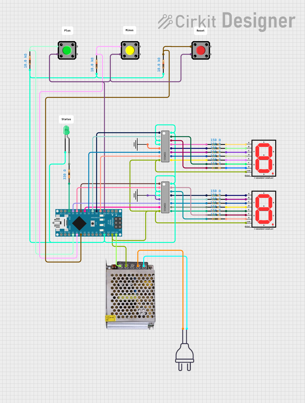
This document provides a detailed overview of a circuit that includes an Arduino Nano microcontroller, a CD4511 BCD to 7-segment latch/decoder/driver, a power supply, resistors, pushbuttons, a 7-segment display, and an LED. The circuit is designed to interface with the 7-segment display and LED through the Arduino Nano, which is powered by a 12V 5A power supply. The pushbuttons are used to provide input to the Arduino, which then drives the display and LED accordingly.
Component List
Microcontroller
- Arduino Nano: A compact microcontroller board based on the ATmega328P, featuring digital and analog I/O pins.
Decoder/Driver
- CD4511: A BCD to 7-segment latch/decoder/driver used to control the 7-segment display.
Power Supply
- POWER SUPPLY 12V 5AMP: Provides a 12V DC output from a 220V AC input.
Resistors
- 150 Ohm Resistors: Used for current limiting to protect components such as LEDs and 7-segment display segments.
- 10k Ohm Resistors: Typically used as pull-up or pull-down resistors for pushbutton inputs.
- 330 Ohm Resistor: Used to limit current through the green LED.
Pushbuttons
- Pushbuttons: Used to provide user input to the microcontroller.
Display
- 7-segment Display: Used to display numerical information, controlled by the CD4511 decoder/driver.
LED
- LED (Green): A simple indicator light.
Ground
- GND: Common ground reference for the circuit.
Wiring Details
Arduino Nano
- Digital pins D2 to D9 are used to interface with the CD4511 decoder/driver.
- Analog pins A0 to A2 are connected to pushbuttons through 10k Ohm resistors.
- The 5V pin provides power to the CD4511 decoder/driver and the green LED through a 330 Ohm resistor.
- The GND pin is connected to the common ground of the circuit.
CD4511 BCD to 7-segment Latch/Decoder/Driver
- Inputs A, B, C, and D are connected to the Arduino Nano digital pins D2 to D9.
- The GND pin is connected to the common ground.
- The VCC pin is connected to the 5V output from the Arduino Nano.
- The ~LT (Lamp Test), ~BL (Blanking), and LE/~STROBE (Latch Enable) pins are tied to the 5V supply through 10k Ohm resistors for normal operation.
- The segment output pins (a to g) are connected to the corresponding segments of the 7-segment display through 150 Ohm resistors.
Power Supply 12V 5AMP
- The 220V AC input is connected to the power supply.
- The 12V DC output is used to power the Arduino Nano through the VIN pin.
- The GND (DC) output is connected to the common ground of the circuit.
Resistors
- 150 Ohm resistors are used to limit current to the 7-segment display segments.
- 10k Ohm resistors are used for the pushbutton inputs and to tie the ~LT, ~BL, and LE/~STROBE pins of the CD4511 to the 5V supply.
- A 330 Ohm resistor is used to limit current through the green LED.
Pushbuttons
- Connected to the Arduino Nano analog pins A0 to A2 through 10k Ohm resistors.
- The other side of the pushbuttons is connected to the common ground.
7-segment Display
- The common pin (COM) is connected to the ground.
- The segment pins (A to G) are connected to the CD4511 output pins through 150 Ohm resistors.
LED (Green)
- The cathode is connected to the ground.
- The anode is connected to the 5V supply through a 330 Ohm resistor.
Documented Code
Arduino Nano Code (sketch.ino)
void setup() {
  // put your setup code here, to run once:

}

void loop() {
  // put your main code here, to run repeatedly:

}
Additional Notes
- The provided code is a template and does not contain any functional implementation. It needs to be populated with the logic to read the pushbutton states and drive the 7-segment display and LED accordingly.
- The documentation text file is empty and can be used to add further notes or explanations about the code and circuit operation.