
ESP32 and Arduino UNO QR Code Reader with LCD Display and Battery-Powered Buck Converter
View and Edit Project In Cirkit Designer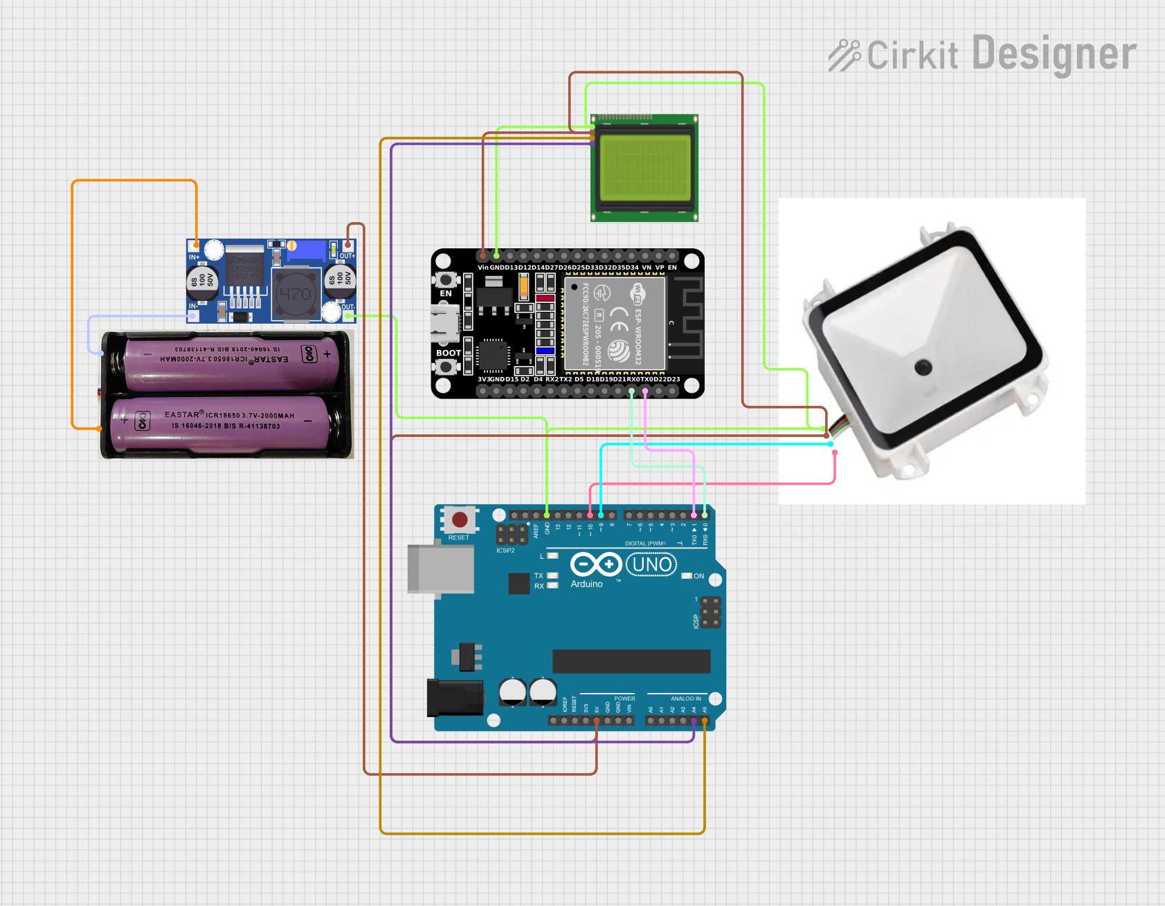
Circuit Documentation
Summary
This document provides a detailed overview of a circuit that includes an ESP32 microcontroller, an Arduino UNO, a QR code reader, an LCD display, a buck converter, and a 7.4V power source. The circuit is designed to interface these components for various functionalities, including reading QR codes and displaying information on an LCD screen.
Component List
ESP32 (30 pin)
- Description: A powerful microcontroller with built-in Wi-Fi and Bluetooth capabilities.
- Pins: EN, VP, VN, D34, D35, D32, D33, D25, D26, D27, D14, D12, D13, GND, Vin, D23, D22, TX0, RX0, D21, D19, D18, D5, TX2, RX2, D4, D2, D15, 3V3
QR Code Reader
- Description: A device used to scan and decode QR codes.
- Pins: GND, 5V, RX, TX
Arduino UNO
- Description: A popular microcontroller board based on the ATmega328P.
- Pins: UNUSED, IOREF, Reset, 3.3V, 5V, GND, Vin, A0, A1, A2, A3, A4, A5, SCL, SDA, AREF, D13, D12, D11, D10, D9, D8, D7, D6, D5, D4, D3, D2, D1, D0
LCD 20x4 I2C
- Description: A 20x4 character LCD display with I2C interface.
- Pins: GND, 5V, SCA, SCL
7.4V Power Source
- Description: A 7.4V battery or power supply.
- Pins: +, -
Buck Converter
- Description: A DC-DC converter used to step down voltage.
- Pins: IN+, IN-, OUT+, OUT-
Wiring Details
ESP32 (30 pin)
- GND is connected to the common ground shared with the Buck Converter, LCD, Arduino UNO, and QR Code Reader.
- Vin is connected to the OUT+ pin of the Buck Converter.
- TX0 is connected to the D1 pin of the Arduino UNO.
- RX0 is connected to the D0 pin of the Arduino UNO.
QR Code Reader
- GND is connected to the common ground shared with the Buck Converter, LCD, Arduino UNO, and ESP32.
- 5V is connected to the OUT+ pin of the Buck Converter.
- RX is connected to the D9 pin of the Arduino UNO.
- TX is connected to the D10 pin of the Arduino UNO.
Arduino UNO
- GND is connected to the common ground shared with the Buck Converter, LCD, QR Code Reader, and ESP32.
- 5V is connected to the OUT+ pin of the Buck Converter.
- D1 is connected to the TX0 pin of the ESP32.
- D0 is connected to the RX0 pin of the ESP32.
- D9 is connected to the RX pin of the QR Code Reader.
- D10 is connected to the TX pin of the QR Code Reader.
- A4 is connected to the SCA pin of the LCD.
- A5 is connected to the SCL pin of the LCD.
LCD 20x4 I2C
- GND is connected to the common ground shared with the Buck Converter, Arduino UNO, QR Code Reader, and ESP32.
- 5V is connected to the OUT+ pin of the Buck Converter.
- SCA is connected to the A4 pin of the Arduino UNO.
- SCL is connected to the A5 pin of the Arduino UNO.
7.4V Power Source
- + is connected to the IN+ pin of the Buck Converter.
- - is connected to the IN- pin of the Buck Converter.
Buck Converter
- IN+ is connected to the + pin of the 7.4V Power Source.
- IN- is connected to the - pin of the 7.4V Power Source.
- OUT+ is connected to the 5V pins of the LCD, Arduino UNO, QR Code Reader, and the Vin pin of the ESP32.
- OUT- is connected to the common ground shared with the LCD, Arduino UNO, QR Code Reader, and ESP32.
Documented Code
Arduino UNO Code
void setup() {
  // put your setup code here, to run once:

}

void loop() {
  // put your main code here, to run repeatedly:

}
This code is a basic template for the Arduino UNO, with empty setup and loop functions. You can add your specific initialization and main code logic within these functions.