
ESP32-CAM and Ultrasonic Sensor-Based Smart Conveyor System with IoT Integration
View and Edit Project In Cirkit Designer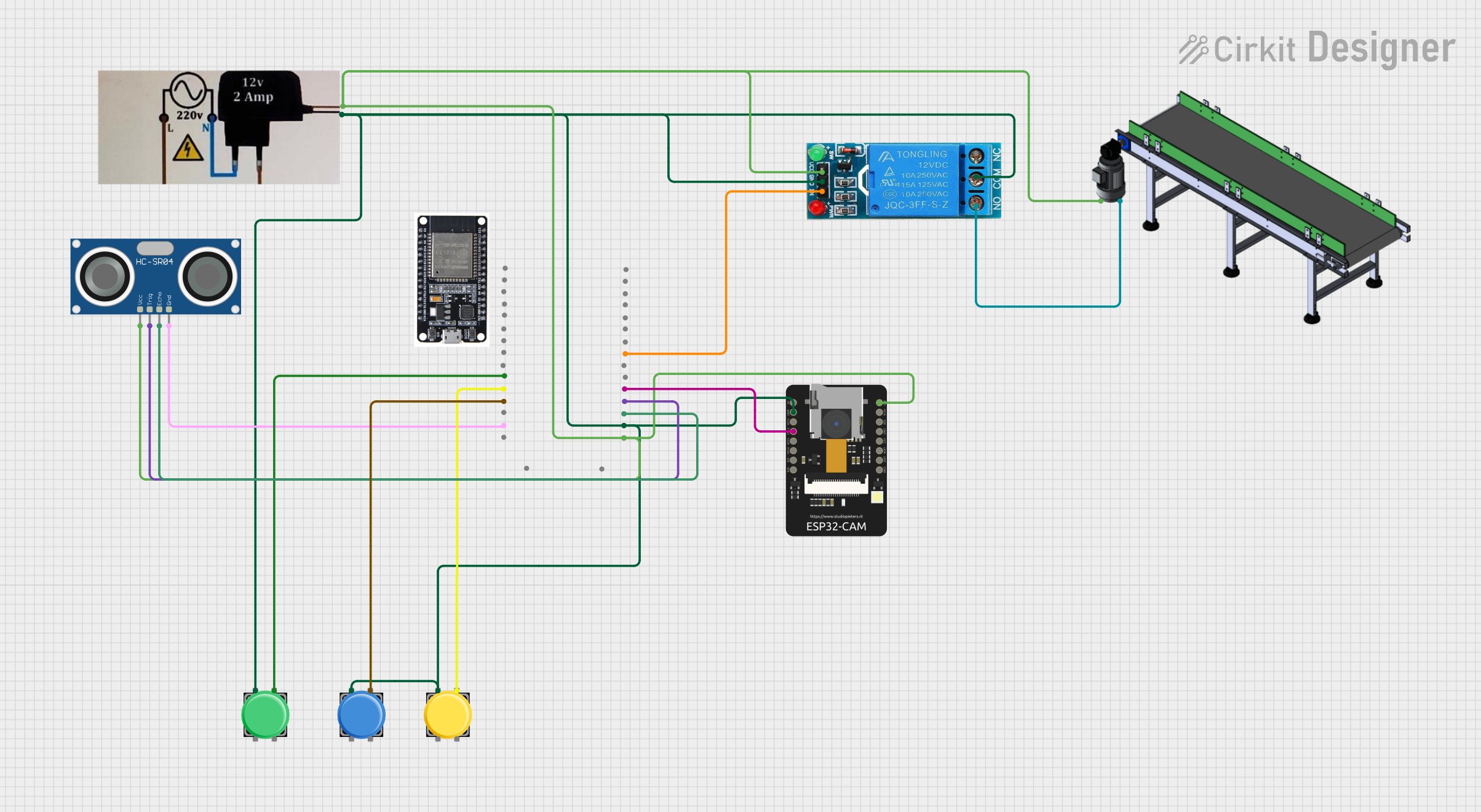
Circuit Documentation
Summary
This circuit is designed to manage a conveyor system for sorting fruits using an ESP32 microcontroller. The system includes pushbuttons, a relay, an ultrasonic sensor, and an ESP32-CAM. The ESP32 microcontroller reads inputs from the pushbuttons and the ultrasonic sensor, controls the relay to manage the conveyor, and interfaces with the ESP32-CAM to capture images.
Component List
Pushbutton
- Description: A simple pushbutton used to provide user input.
- Pins: Pin 1, Pin 2, Pin 3, Pin 4
12V Single Channel Relay
- Description: A relay module used to control the conveyor motor.
- Pins: NC, COM, NO, IN, GND, VCC
12V Power Supply
- Description: Provides 12V power to the circuit.
- Pins: Positive, Negative
Conveyor
- Description: A conveyor belt system used to transport fruits.
- Pins: Positive, Negative
ESP32 - CAM
- Description: A microcontroller with a built-in camera module.
- Pins: 5V, GND, IO12, IO13, IO15, IO14, IO2, IO4, VOT, VOR, VCC, IO0, IO16, 3V3
HC-SR04 Ultrasonic Sensor
- Description: An ultrasonic sensor used to measure the distance of objects.
- Pins: VCC, TRIG, ECHO, GND
ESP32
- Description: A microcontroller used to control the entire system.
- Pins: EN, VP, VN, D34, D35, D32, D33, D25, D26, D27, D14, D12, D13, GND, VIN, 3V3, D15, D2, D4, RX2, TX2, D5, D18, D19, D21, RX0, TX0, D22, D23, BOOT
Wiring Details
Pushbutton 1
- Pin 1: Connected to the negative terminal of the 12V power supply.
- Pin 3: Connected to D12 of the ESP32.
Pushbutton 2
- Pin 1: Connected to the negative terminal of the 12V power supply.
- Pin 3: Connected to D14 of the ESP32.
Pushbutton 3
- Pin 1: Connected to the negative terminal of the 12V power supply.
- Pin 3: Connected to D27 of the ESP32.
12V Single Channel Relay
- COM: Connected to the negative terminal of the 12V power supply.
- GND: Connected to the negative terminal of the 12V power supply.
- NO: Connected to the negative terminal of the conveyor.
- IN: Connected to D5 of the ESP32.
- VCC: Connected to the positive terminal of the 12V power supply.
12V Power Supply
- Positive: Connected to the positive terminal of the conveyor, VCC of the HC-SR04 Ultrasonic Sensor, VCC of the 12V Single Channel Relay, 3V3 of the ESP32 - CAM, and 3V3 of the ESP32.
- Negative: Connected to Pin 1 of all pushbuttons, COM and GND of the 12V Single Channel Relay, GND of the ESP32 - CAM, and GND of the ESP32.
Conveyor
- Positive: Connected to the positive terminal of the 12V power supply.
- Negative: Connected to NO of the 12V Single Channel Relay.
ESP32 - CAM
- GND: Connected to the negative terminal of the 12V power supply.
- 3V3: Connected to the positive terminal of the 12V power supply.
- IO13: Connected to D4 of the ESP32.
HC-SR04 Ultrasonic Sensor
- VCC: Connected to the positive terminal of the 12V power supply.
- GND: Connected to GND of the ESP32.
- ECHO: Connected to D15 of the ESP32.
- TRIG: Connected to D2 of the ESP32.
ESP32
- GND: Connected to the negative terminal of the 12V power supply.
- 3V3: Connected to the positive terminal of the 12V power supply.
- D12: Connected to Pin 3 of Pushbutton 1.
- D14: Connected to Pin 3 of Pushbutton 2.
- D27: Connected to Pin 3 of Pushbutton 3.
- D4: Connected to IO13 of the ESP32 - CAM.
- D5: Connected to IN of the 12V Single Channel Relay.
- D15: Connected to ECHO of the HC-SR04 Ultrasonic Sensor.
- D2: Connected to TRIG of the HC-SR04 Ultrasonic Sensor.
Documented Code
/*
 * Advanced Sorting Fruit with IoT and Artificial Intelligence
 * This code controls an ESP32 microcontroller to manage a conveyor system
 * with pushbuttons, a relay, an ultrasonic sensor, and an ESP32-CAM.
 * The system sorts fruits based on distance measurements and captures images.
 */

#define BUTTON1_PIN 12
#define BUTTON2_PIN 14
#define BUTTON3_PIN 27
#define RELAY_PIN 5
#define TRIG_PIN 2
#define ECHO_PIN 15
#define CAM_PIN 4

void setup() {
  pinMode(BUTTON1_PIN, INPUT);
  pinMode(BUTTON2_PIN, INPUT);
  pinMode(BUTTON3_PIN, INPUT);
  pinMode(RELAY_PIN, OUTPUT);
  pinMode(TRIG_PIN, OUTPUT);
  pinMode(ECHO_PIN, INPUT);
  pinMode(CAM_PIN, OUTPUT);
  Serial.begin(115200);
}

long readUltrasonicDistance() {
  digitalWrite(TRIG_PIN, LOW);
  delayMicroseconds(2);
  digitalWrite(TRIG_PIN, HIGH);
  delayMicroseconds(10);
  digitalWrite(TRIG_PIN, LOW);
  long duration = pulseIn(ECHO_PIN, HIGH);
  long distance = duration * 0.034 / 2;
  return distance;
}

void loop() {
  if (digitalRead(BUTTON1_PIN) == HIGH) {
    Serial.println("Button 1 Pressed");
  }
  if (digitalRead(BUTTON2_PIN) == HIGH) {
    Serial.println("Button 2 Pressed");
  }
  if (digitalRead(BUTTON3_PIN) == HIGH) {
    Serial.println("Button 3 Pressed");
  }
  long distance = readUltrasonicDistance();
  Serial.print("Distance: ");
  Serial.print(distance);
  Serial.println(" cm");
  if (distance < 10) {
    digitalWrite(RELAY_PIN, HIGH);
    Serial.println("Relay ON");
  } else {
    digitalWrite(RELAY_PIN, LOW);
    Serial.println("Relay OFF");
  }
  delay(1000);
}
This code initializes the pins for the pushbuttons, relay, ultrasonic sensor, and ESP32-CAM. It reads the state of the pushbuttons and the distance from the ultrasonic sensor, controlling the relay based on the distance measurement. The code also prints the status of the pushbuttons and the distance measurement to the serial monitor.