Arduino-Controlled Motor System with Bluetooth Connectivity
Circuit Documentation
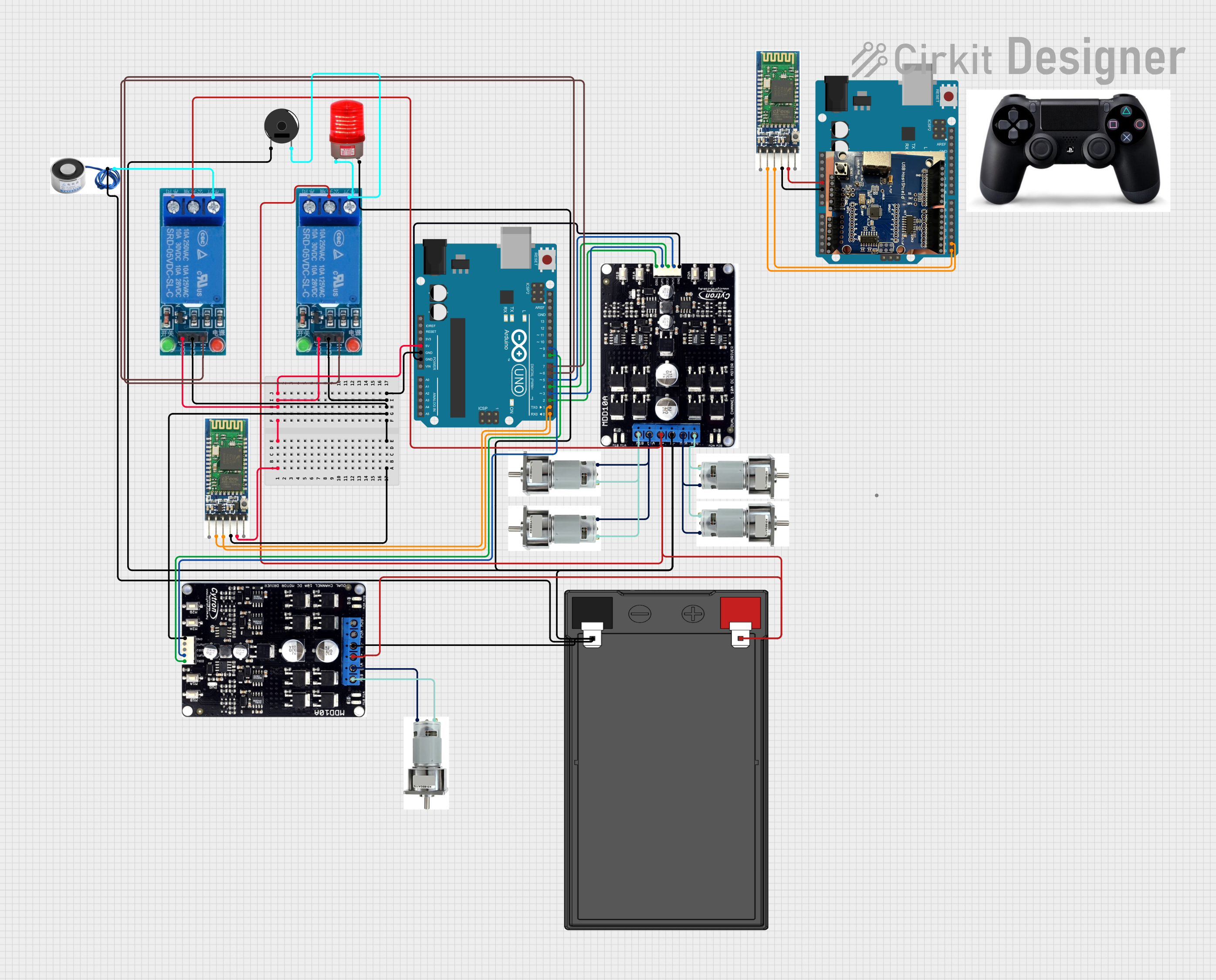
Summary
This circuit is designed to control multiple Johnson motors using Cytron motor drivers, which are interfaced with Arduino UNO microcontrollers. The circuit includes relay modules to switch external devices like a red light and a piezo buzzer. A Bluetooth module is used for wireless communication. The power is supplied by a 12V 7Ah battery. The circuit appears to be part of a larger system, potentially a robotic or automation project, given the use of motors and wireless communication.
Component List
Microcontrollers
- Arduino UNO: A microcontroller board based on the ATmega328P, featuring digital and analog I/O pins.
Motor Drivers
- Cytron: A motor driver capable of driving bidirectional DC motors with direction and speed control.
Motors
- Johnson Motor: A DC motor used for various mechanical movements in the circuit.
Power Supply
- 12V 7Ah Battery: Provides the main power source for the motors and the motor drivers.
Relay Modules
- Relay 5V Single Connection: Used to control high power devices such as the red light and piezo buzzer.
Indicators and Sound Devices
- Red Light 220VAC: An indicator light that operates at 220V AC.
- Piezo Buzzer: An electronic device that emits a tone when powered.
Communication Modules
- Bluetooth: A wireless communication module for transferring data between devices.
Miscellaneous
- USB HOST SHIELD 2.0: An add-on board for Arduino UNO, allowing USB devices to be connected to the microcontroller.
- PS4: A component with unspecified functionality in the provided list.
Wiring Details
Arduino UNO
- 5V and GND pins are used to power the relay modules and the Bluetooth module.
- Digital pins D0-D9 are used for communication with the Bluetooth module, controlling the Cytron motor drivers, and interfacing with the relay modules.
Cytron Motor Driver
- B+ and B- pins are connected to the 12V battery for power.
- M1A, M1B, M2A, and M2B pins are connected to the Johnson motors for driving them.
- DIR1, DIR2, PWM1, and PWM2 pins are connected to the Arduino UNO for direction and speed control.
- GND is connected to the common ground.
Johnson Motor
- The motors are connected to the Cytron motor driver for control.
12V 7Ah Battery
- Provides power to the Cytron motor drivers and through them to the motors.
Relay 5V Single Connection
- VCC and GND are connected to the 5V and GND of the Arduino UNO for power.
- IN pins are connected to the Arduino UNO for control signals.
- NO and COMM pins are used to switch the red light and piezo buzzer.
Red Light 220VAC
- Connected to one of the relay modules for switching on and off.
Piezo Buzzer
- Connected to one of the relay modules for activation.
Bluetooth Module
- VCC and GND are connected to the 5V and GND of the Arduino UNO for power.
- TXD and RXD are connected to the D0 and D1 pins of the Arduino UNO for serial communication.
Documented Code
Arduino UNO (Main Controller)
void setup() {
  // put your setup code here, to run once:

}

void loop() {
  // put your main code here, to run repeatedly:

}
Note: The actual functionality within the setup and loop functions is not provided in the input code.
Arduino UNO (Secondary Controller)
void setup() {
  // put your setup code here, to run once:

}

void loop() {
  // put your main code here, to run repeatedly:

}
Note: The actual functionality within the setup and loop functions is not provided in the input code.
Additional documentation files were mentioned but contained no content.