
Raspberry Pi 4B-Controlled Relay System with Environmental Sensing and Power Monitoring
View and Edit Project In Cirkit Designer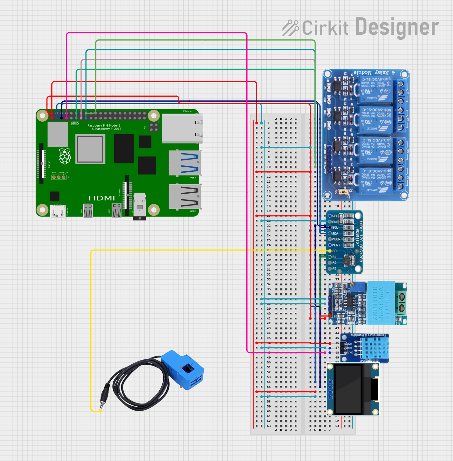
Circuit Documentation
Summary of the Circuit
This circuit is designed to interface a Raspberry Pi 4B with various sensors and output devices, including a 4-channel relay, an ADS1115 analog-to-digital converter (ADC), a current sensor, a DHT11 temperature and humidity sensor, a ZMPT101B voltage sensor, and a 0.96" OLED display. The Raspberry Pi 4B serves as the central processing unit, controlling the relay channels and communicating with the I2C devices (ADS1115 and OLED display). The ADS1115 is used to read analog signals from the current and voltage sensors, while the DHT11 and ZMPT101B provide environmental and voltage data, respectively. The relay allows the Raspberry Pi to control higher power loads.
Component List
Relay 4 Channel 5v
- Description: A 4-channel relay module capable of controlling up to four separate high-power circuits.
- Pins: GND, IN1, IN2, IN3, IN4, VCC, COM1, COM2, COM3, COM4, NO1, NO2, NO3, NO4, NC1, NC2, NC3, NC4
ADS1115
- Description: A precision analog-to-digital converter (ADC) with 16-bit resolution used for reading analog signals.
- Pins: VDD, GND, SCL, SDA, ADDR, ALRT, A0, A1, A2, A3
Current Sensor
- Description: A sensor used to measure electrical current flowing through a conductor.
- Pins: Out, Burden, In_current, Out_current
DHT11
- Description: A basic, low-cost digital temperature and humidity sensor.
- Pins: DATA, GND, VCC
ZMPT101B
- Description: A module for voltage measurement in AC power networks.
- Pins: OUT, GND, VCC, NEUTRO, FASE
0.96" OLED
- Description: A small OLED display for visual output.
- Pins: GND, VDD, SCK, SDA
Raspberry Pi 4B
- Description: A small single-board computer with GPIO pins for interfacing with various electronic components.
- Pins: 3V3, 5V, GPIO2, GPIO3, GND, GPIO4, GPIO14, GPIO15, GPIO17, GPIO18, GPIO27, GPIO22, GPIO23, GPIO24, GPIO10, GPIO9, GPIO25, GPIO11, GPIO8, GPIO7, ID_SD, GPIO5, GPIO6, GPIO12, GPIO13, GPIO19, GPIO16, GPIO26, GPIO20, GPIO21, ID_SC, TR01_TAP, TR00_TAP, TR03_TAP, TR02_TAP, RUN, GLOBAL_EN
Wiring Details
Relay 4 Channel 5v
- GND: Connected to system ground.
- IN1: Controlled by Raspberry Pi GPIO17.
- IN2: Controlled by Raspberry Pi GPIO27.
- IN3: Controlled by Raspberry Pi GPIO22.
- IN4: Controlled by Raspberry Pi GPIO23.
- VCC: Powered by Raspberry Pi 3V3.
ADS1115
- VDD: Powered by Raspberry Pi 3V3.
- GND: Connected to system ground.
- SCL: Connected to Raspberry Pi GPIO3 (I2C clock).
- SDA: Connected to Raspberry Pi GPIO2 (I2C data).
- A0: Connected to the output of the current sensor.
- A1: Connected to the output of the ZMPT101B voltage sensor.
Current Sensor
- Out: Connected to ADS1115 A0.
DHT11
- DATA: Connected to Raspberry Pi GPIO4.
- GND: Connected to system ground.
- VCC: Powered by Raspberry Pi 3V3.
ZMPT101B
- OUT: Connected to ADS1115 A1.
- GND: Connected to system ground.
- VCC: Powered by Raspberry Pi 5V.
0.96" OLED
- GND: Connected to system ground.
- VDD: Powered by Raspberry Pi 3V3.
- SCK: Connected to Raspberry Pi GPIO3 (I2C clock).
- SDA: Connected to Raspberry Pi GPIO2 (I2C data).
Raspberry Pi 4B
- 3V3: Provides power to Relay 4 Channel 5v, ADS1115, DHT11, and 0.96" OLED.
- 5V: Provides power to ZMPT101B.
- GPIO2: I2C data for ADS1115 and 0.96" OLED.
- GPIO3: I2C clock for ADS1115 and 0.96" OLED.
- GPIO4: Data for DHT11.
- GPIO17, GPIO27, GPIO22, GPIO23: Control signals for Relay 4 Channel 5v.
Documented Code
No code was provided for the microcontrollers in the circuit. Therefore, this section is not applicable for the current documentation. If code becomes available, it should be documented here with descriptions of its functionality and how it interfaces with the hardware components listed above.