Arduino UNO Controlled Dual-Motor Car with Joystick and L298N Driver
Circuit Documentation
Summary
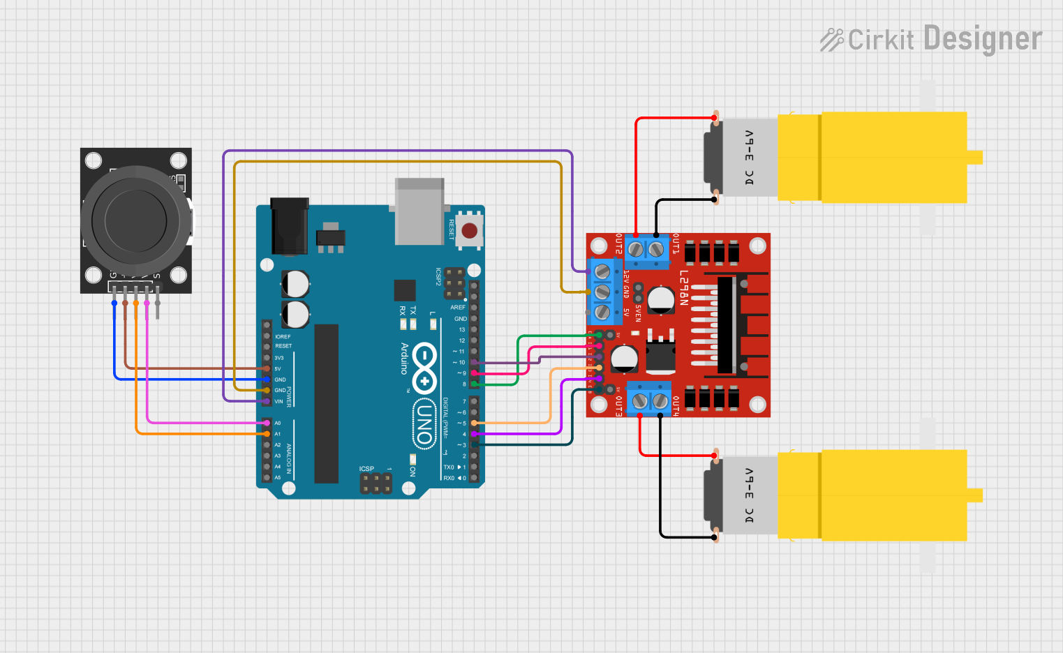
This circuit is designed to control a car using an Arduino UNO microcontroller and a dual-axis joystick module (KY-023) for user input. The Arduino UNO reads the joystick's position and sends commands to an L298N DC motor driver, which in turn controls two yellow hobby gear motors. The motors enable the car to move forward, backward, turn left, and turn right. The circuit is powered by the Arduino UNO, which also provides power to the joystick and motor driver.
Component List
Arduino UNO
- Microcontroller board based on the ATmega328P
- Provides digital and analog I/O pins
- Can be powered via USB or external power supply
Motor Amarillo Motorreductor Hobby (x2)
- Yellow hobby gear motor
- Operates on a voltage supply (typically 3V to 6V)
L298N DC Motor Driver
- Dual H-bridge motor driver
- Capable of driving two DC motors or one stepper motor
- Provides pins for motor control inputs and power supply
KY-023 Dual Axis Joystick Module
- Joystick with two analog outputs (VRx and VRy) for X and Y-axis
- Includes a pushbutton switch (SW)
- Operates on +5V supply
Wiring Details
Arduino UNO
5Vpin connected to the+5Vpin of the KY-023 Joystick ModuleGNDpin connected to theGNDpin of the KY-023 Joystick Module andGNDpin of the L298N Motor DriverVinpin connected to the12Vpin of the L298N Motor DriverA0pin connected to theVRypin of the KY-023 Joystick ModuleA1pin connected to theVRxpin of the KY-023 Joystick ModuleD10pin connected to theIN2pin of the L298N Motor DriverD9pin connected to theIN1pin of the L298N Motor DriverD8pin connected to theENApin of the L298N Motor DriverD5pin connected to theIN3pin of the L298N Motor DriverD4pin connected to theIN4pin of the L298N Motor DriverD3pin connected to theENBpin of the L298N Motor Driver
Motor Amarillo Motorreductor Hobby
- First motor:
vccpin connected toOUT2andGNDpin connected toOUT1of the L298N Motor Driver - Second motor:
vccpin connected toOUT3andGNDpin connected toOUT4of the L298N Motor Driver
L298N DC Motor Driver
GNDpin connected to theGNDpin of the Arduino UNO12Vpin connected to theVinpin of the Arduino UNOIN1,IN2,IN3,IN4,ENA, andENBpins connected to the corresponding digital pins on the Arduino UNOOUT1,OUT2,OUT3, andOUT4pins connected to the respective motor pins
KY-023 Dual Axis Joystick Module
+5Vpin connected to the5Vpin of the Arduino UNOGNDpin connected to theGNDpin of the Arduino UNOVRxpin connected to theA1pin of the Arduino UNOVRypin connected to theA0pin of the Arduino UNO
Documented Code
/*
 * Arduino Sketch for controlling a car using Bluetooth technology.
 * This code reads commands from the Serial input (Bluetooth module) and
 * controls the car's movement accordingly. The car can move forward,
 * backward, turn left, turn right, and stop based on the received commands.
 */

int Input_Pin_4 = 4; // Connected to IN4 on L298N
int Input_Pin_3 = 5; // Connected to IN3 on L298N
int Input_Pin_2 = 6; // Connected to IN2 on L298N
int Input_Pin_1 = 7; // Connected to IN1 on L298N
char Value;

void setup() {
  pinMode(Input_Pin_4, OUTPUT);  // Digital pin 4
  pinMode(Input_Pin_3, OUTPUT);  // Digital pin 5
  pinMode(Input_Pin_2, OUTPUT);  // Digital pin 6
  pinMode(Input_Pin_1, OUTPUT);  // Digital pin 7
  Serial.begin(9600);
}

void loop() {
  while (Serial.available() > 0) {
    Value = Serial.read();
    Serial.println(Value);
  }
  if (Value == 'F') {
    // Move Forward
    digitalWrite(Input_Pin_1, HIGH);
    digitalWrite(Input_Pin_2, LOW);
    digitalWrite(Input_Pin_3, HIGH);
    digitalWrite(Input_Pin_4, LOW);
  } else if (Value == 'B') {
    // Move Backward
    digitalWrite(Input_Pin_1, LOW);
    digitalWrite(Input_Pin_2, HIGH);
    digitalWrite(Input_Pin_3, LOW);
    digitalWrite(Input_Pin_4, HIGH);
  } else if (Value == 'L') {
    // Turn Left
    digitalWrite(Input_Pin_1, LOW);
    digitalWrite(Input_Pin_2, LOW);
    digitalWrite(Input_Pin_3, HIGH);
    digitalWrite(Input_Pin_4, LOW);
  } else if (Value == 'R') {
    // Turn Right
    digitalWrite(Input_Pin_1, HIGH);
    digitalWrite(Input_Pin_2, LOW);
    digitalWrite(Input_Pin_3, LOW);
    digitalWrite(Input_Pin_4, LOW);
  } else if (Value == 'S') {
    // Stop
    digitalWrite(Input_Pin_1, LOW);
    digitalWrite(Input_Pin_2, LOW);
    digitalWrite(Input_Pin_3, LOW);
    digitalWrite(Input_Pin_4, LOW);
  }
}
This code is designed to be uploaded to the Arduino UNO microcontroller. It sets up the digital pins connected to the L298N motor driver as outputs and initializes serial communication. The loop function reads a character from the serial input and controls the motors' direction and speed accordingly.