
Traffic Light Control Circuit Documentation
Summary
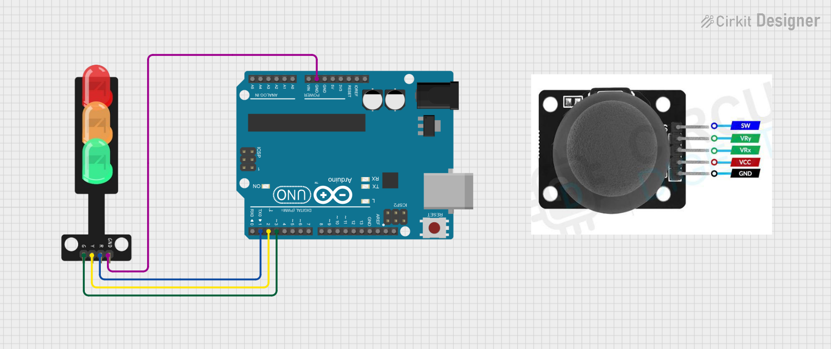
This document describes a simple traffic light control system using an Arduino UNO microcontroller and a traffic light module. The system operates a sequence of lights: red, yellow, and green, each for a specific duration. The Arduino UNO controls the traffic light by turning on and off the respective LEDs in a predefined sequence. The circuit also includes a joystick module, although it is not connected in the current configuration.
Component List
Arduino UNO
- Description: A microcontroller board based on the ATmega328P.
- Purpose: Acts as the central controller for the traffic light system, driving the LEDs and managing the timing of the light sequence.
- Pins: UNUSED, IOREF, Reset, 3.3V, 5V, GND, Vin, A0-A5, SCL, SDA, AREF, D0-D13
Traffic Light
- Description: A module with three LEDs representing a traffic light system.
- Purpose: Displays the traffic light sequence controlled by the Arduino UNO.
- Pins: Green, Yellow, Red, GND
Joystick Module
- Description: An input device with two axes of control and a pushbutton.
- Purpose: Not used in the current circuit configuration.
- Pins: SW, VRY, VRX, VCC, GND
Wiring Details
Arduino UNO
- GND connected to Traffic Light GND
- D3 connected to Traffic Light Green LED
- D2 connected to Traffic Light Yellow LED
- D1 connected to Traffic Light Red LED
Traffic Light
- GND connected to Arduino UNO GND
- Green connected to Arduino UNO D3
- Yellow connected to Arduino UNO D2
- Red connected to Arduino UNO D1
Joystick Module
- Currently not connected in the circuit.
Documented Code
/*
 * This Arduino sketch controls a traffic light system.
 * The traffic light has three LEDs: Red, Yellow, and Green.
 * The sequence is as follows:
 * - Red LED is on for 5 seconds
 * - Yellow LED is on for 2 seconds
 * - Green LED is on for 5 seconds
 * This sequence repeats indefinitely.
 */

// Pin definitions
const int redLedPin = 1;    // Red LED connected to digital pin 1
const int yellowLedPin = 2; // Yellow LED connected to digital pin 2
const int greenLedPin = 3;  // Green LED connected to digital pin 3

void setup() {
  // Initialize the LED pins as outputs
  pinMode(redLedPin, OUTPUT);
  pinMode(yellowLedPin, OUTPUT);
  pinMode(greenLedPin, OUTPUT);
}

void loop() {
  // Turn on the Red LED
  digitalWrite(redLedPin, HIGH);
  delay(5000); // Wait for 5 seconds
  digitalWrite(redLedPin, LOW);

  // Turn on the Yellow LED
  digitalWrite(yellowLedPin, HIGH);
  delay(2000); // Wait for 2 seconds
  digitalWrite(yellowLedPin, LOW);

  // Turn on the Green LED
  digitalWrite(greenLedPin, HIGH);
  delay(5000); // Wait for 5 seconds
  digitalWrite(greenLedPin, LOW);
}
Filename: sketch.ino
This code is responsible for controlling the traffic light sequence. It initializes the digital pins connected to the LEDs as outputs and then enters a loop where it turns each LED on and off in sequence with delays to represent the duration each light is on. The red LED is on for 5 seconds, followed by the yellow LED for 2 seconds, and the green LED for 5 seconds. This cycle repeats indefinitely.