
Arduino 101 Based Metal Detection and GPS Tracking System with RF Communication
View and Edit Project In Cirkit Designer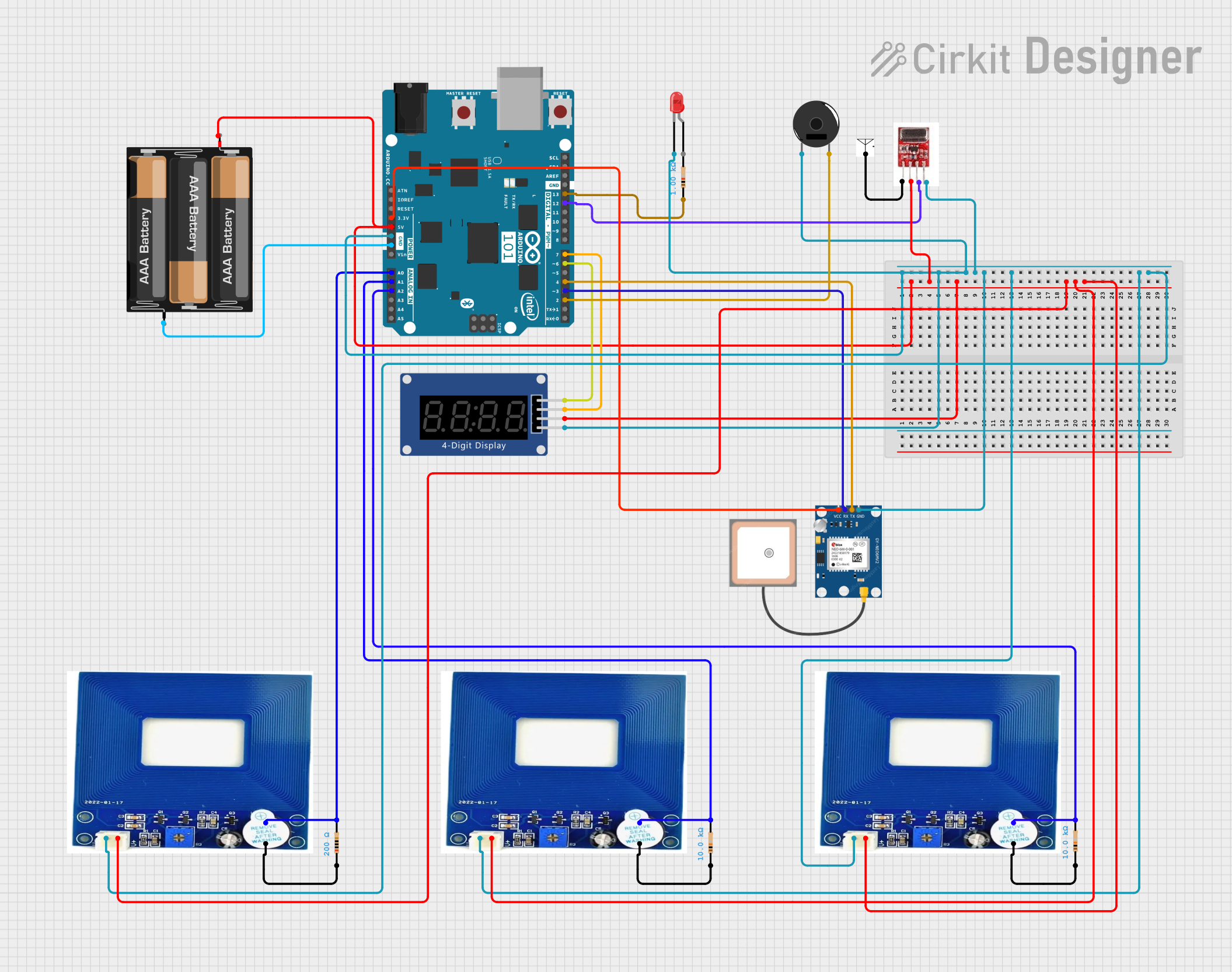
Circuit Documentation
Summary
The circuit described in the provided inputs consists of an Arduino 101 microcontroller that interfaces with a variety of components including metal detectors, a seven-segment display, a piezo buzzer, an LED, an RF module transmitter, and a GPS module. The circuit is powered by a 3xAA battery pack. The metal detectors are used to detect the presence of metallic objects, and their signals are processed by the Arduino. The seven-segment display shows output data, while the piezo buzzer and LED can provide audio and visual alerts, respectively. The RF module allows for wireless data transmission, and the GPS module provides location data. The circuit is designed for applications that require metal detection, data display, and location tracking capabilities.
Component List
Metal Detector
- Description: A sensor that detects metallic objects.
- Pins: VCC, GND, DATA
Resistor (10k Ohms)
- Description: A passive two-terminal electrical component that implements electrical resistance as a circuit element.
- Resistance: 10,000 Ohms
Resistor (200 Ohms)
- Description: A passive two-terminal electrical component that implements electrical resistance as a circuit element.
- Resistance: 200 Ohms
3xAA Battery
- Description: A power source for the circuit.
- Pins: VCC, GND
Arduino 101
- Description: A microcontroller board based on the Intel Curie Module.
- Pins: Various digital and analog pins, power, and ground.
LED: Two Pin (red)
- Description: A red light-emitting diode.
- Pins: cathode, anode
Piezo Buzzer
- Description: An electronic device that produces sound.
- Pins: pin 1, pin 2
RF Module Transmitter
- Description: A wireless transmitter for sending data.
- Pins: ANT, VCC, DAT, GND
Seven Segment Display (TM1637)
- Description: A display module for representing numerical data.
- Pins: CLK, DIO, VCC, GND
Resistor (1k Ohms)
- Description: A passive two-terminal electrical component that implements electrical resistance as a circuit element.
- Resistance: 1,000 Ohms
Antenna
- Description: A device for transmitting or receiving radio waves.
GPS NEO 6M
- Description: A GPS module for obtaining geographical location data.
- Pins: VCC, RX, TX, GND
Wiring Details
Metal Detector
- VCC connected to 3xAA Battery VCC.
- GND connected to Arduino 101 GND.
- DATA connected to Arduino 101 analog pins (A0, A1, A2) through 10k Ohm resistors.
Resistor (10k Ohms)
- One end connected to Metal Detector DATA pin.
- Other end connected to Arduino 101 analog pins (A0, A1, A2) and GND.
Resistor (200 Ohms)
- One end connected to Metal Detector DATA pin.
- Other end connected to GND.
3xAA Battery
- VCC connected to Arduino 101 5V and various VCC pins of other components.
- GND connected to Arduino 101 GND.
Arduino 101
- Various I/O pins connected to components as per the net list.
LED: Two Pin (red)
- Cathode connected to Arduino 101 GND.
- Anode connected to Arduino 101 through a 1k Ohm resistor.
Piezo Buzzer
- Pin 1 connected to Arduino 101 GND.
- Pin 2 connected to Arduino 101 D2.
RF Module Transmitter
- ANT connected to Antenna.
- VCC connected to 3xAA Battery VCC.
- DAT connected to Arduino 101 D12/MISO.
- GND connected to Arduino 101 GND.
Seven Segment Display (TM1637)
- CLK connected to Arduino 101 D6 PWM.
- DIO connected to Arduino 101 D7.
- VCC connected to 3xAA Battery VCC.
- GND connected to Arduino 101 GND.
Resistor (1k Ohms)
- One end connected to Arduino 101 D13/SCK.
- Other end not specified (possibly to LED anode).
Antenna
- Connected to RF Module Transmitter ANT.
GPS NEO 6M
- VCC connected to Arduino 101 3V3.
- RX connected to Arduino 101 D3 PWM.
- TX connected to Arduino 101 D4.
- GND connected to Arduino 101 GND.
Documented Code
No code was provided in the input. Therefore, this section is not applicable for the current documentation.