
ESP32-Based Smart Irrigation System with Water Level and NPK Soil Sensors
View and Edit Project In Cirkit Designer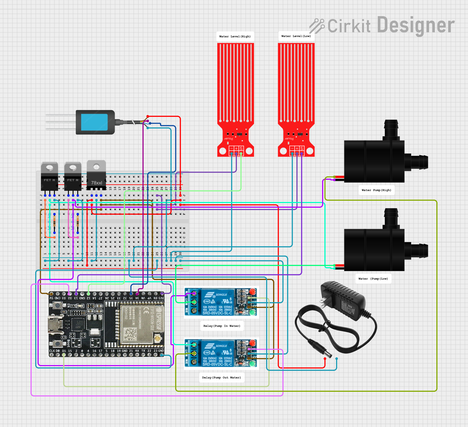
Circuit Documentation
Summary
This circuit is designed to control water pumps based on the readings from water level sensors and an NPK soil sensor. The system uses an ESP32 microcontroller to read sensor data and control relays that activate the water pumps. The circuit also includes a voltage regulator to step down the voltage from a 12V power supply to 5V for the relays and the ESP32.
Component List
5V Relay
- Pins: Normally Open, Common terminal, Normally Closed, In, GND, VCC
- Description: Used to control the water pumps based on signals from the ESP32.
Water Pump
- Pins: VCC, GND
- Description: Pumps water when activated by the relay.
Water Level Sensor
- Pins: SIG, VCC, GND
- Description: Measures the water level and sends the data to the ESP32.
12V Power Supply
- Pins: +, -
- Description: Provides 12V power to the circuit.
nMOS Transistor (MOSFET)
- Pins: gate, drain, source
- Description: Used for switching and amplification.
Voltage Regulator
- Pins: IN, GND, OUT
- Description: Steps down the voltage from 12V to 5V.
Resistor
- Pins: pin1, pin2
- Description: 10k Ohm resistors used for current limiting and voltage division.
ESP32-WROOM-32UE
- Pins: 3v3, EN, VP, VN, 34, 35, 32, 33, 25, 26, 27, 14, 12, GND, 13, D2, D3, 5V, 23, 22, TX, RX, 21, 19, 18, 5, 17, 16, 4, 0, 2, 15, D1, D0, CKL
- Description: Microcontroller used to read sensor data and control the relays.
NPK Soil Sensor
- Pins: 12V DC, A, B, GND
- Description: Measures the nutrient content in the soil.
Wiring Details
5V Relay
- Normally Open: Connected to the drain of the nMOS Transistor (MOSFET).
- Common terminal: Connected to the VCC of the Water Pump.
- Normally Closed: Not used.
- In: Connected to D1 and D2 pins of the ESP32.
- GND: Connected to the common ground.
- VCC: Connected to the output of the Voltage Regulator.
Water Pump
- VCC: Connected to the Common terminal of the 5V Relay.
- GND: Connected to the drain of the nMOS Transistor (MOSFET).
Water Level Sensor
- SIG: Connected to pins 12 and 13 of the ESP32.
- VCC: Connected to the 3v3 pin of the ESP32.
- GND: Connected to the common ground.
12V Power Supply
- +: Connected to the input of the Voltage Regulator and the 12V DC pin of the NPK Soil Sensor.
- -: Connected to the common ground.
nMOS Transistor (MOSFET)
- gate: Connected to pin1 of the Resistor.
- drain: Connected to the Normally Open pin of the 5V Relay.
- source: Connected to the common ground.
Voltage Regulator
- IN: Connected to the + pin of the 12V Power Supply.
- GND: Connected to the common ground.
- OUT: Connected to the VCC pin of the 5V Relay and the 5V pin of the ESP32.
Resistor
- pin1: Connected to the gate of the nMOS Transistor (MOSFET).
- pin2: Connected to the common ground.
ESP32-WROOM-32UE
- 3v3: Connected to the VCC pin of the Water Level Sensor.
- GND: Connected to the common ground.
- 5V: Connected to the output of the Voltage Regulator.
- D1: Connected to the In pin of the 5V Relay.
- D2: Connected to the In pin of the 5V Relay.
- 12: Connected to the SIG pin of the Water Level Sensor.
- 13: Connected to the SIG pin of the Water Level Sensor.
- 34: Connected to the A pin of the NPK Soil Sensor.
- 35: Connected to the B pin of the NPK Soil Sensor.
NPK Soil Sensor
- 12V DC: Connected to the + pin of the 12V Power Supply.
- A: Connected to pin 34 of the ESP32.
- B: Connected to pin 35 of the ESP32.
- GND: Connected to the common ground.
Code Documentation
// Define pin connections
#define WATER_LEVEL_SENSOR_1_PIN 12
#define WATER_LEVEL_SENSOR_2_PIN 13
#define RELAY_1_PIN D1
#define RELAY_2_PIN D2
#define NPK_SENSOR_ANALOG_PIN 34
#define NPK_SENSOR_DIGITAL_PIN 35

// Threshold values for water level sensors
#define WATER_LEVEL_THRESHOLD 500  // Adjust this value based on your sensor's output

void setup() {
  // Initialize serial communication
  Serial.begin(115200);

  // Initialize water level sensor pins as input
  pinMode(WATER_LEVEL_SENSOR_1_PIN, INPUT);
  pinMode(WATER_LEVEL_SENSOR_2_PIN, INPUT);

  // Initialize relay pins as output
  pinMode(RELAY_1_PIN, OUTPUT);
  pinMode(RELAY_2_PIN, OUTPUT);

  // Initialize NPK sensor pins
  pinMode(NPK_SENSOR_ANALOG_PIN, INPUT);
  pinMode(NPK_SENSOR_DIGITAL_PIN, INPUT);

  // Turn off relays initially
  digitalWrite(RELAY_1_PIN, LOW);
  digitalWrite(RELAY_2_PIN, LOW);
}

void loop() {
  // Read water level sensor values
  int waterLevel1 = analogRead(WATER_LEVEL_SENSOR_1_PIN);
  int waterLevel2 = analogRead(WATER_LEVEL_SENSOR_2_PIN);

  // Read NPK sensor values
  int npkAnalogValue = analogRead(NPK_SENSOR_ANALOG_PIN);
  int npkDigitalValue = digitalRead(NPK_SENSOR_DIGITAL_PIN);

  // Print sensor values to serial monitor
  Serial.print("Water Level Sensor 1: ");
  Serial.println(waterLevel1);
  Serial.print("Water Level Sensor 2: ");
  Serial.println(waterLevel2);
  Serial.print("NPK Sensor Analog Value: ");
  Serial.println(npkAnalogValue);
  Serial.print("NPK Sensor Digital Value: ");
  Serial.println(npkDigitalValue);

  // Control water pumps based on water level sensor readings
  if (waterLevel1 < WATER_LEVEL_THRESHOLD) {
    digitalWrite(RELAY_1_PIN, HIGH);  // Turn on pump 1
  } else {
    digitalWrite(RELAY_1_PIN, LOW);   // Turn off pump 1
  }

  if (waterLevel2 < WATER_LEVEL_THRESHOLD) {
    digitalWrite(RELAY_2_PIN, HIGH);  // Turn on pump 2
  } else {
    digitalWrite(RELAY_2_PIN, LOW);   // Turn off pump 2
  }

  // Add a delay to avoid flooding the serial monitor
  delay(1000);
}
This code initializes the pins for the water level sensors, relays, and NPK sensor. It reads the sensor values and controls the relays to turn the water pumps on or off based on the water level readings. The sensor values are also printed to the serial monitor for debugging and monitoring purposes.