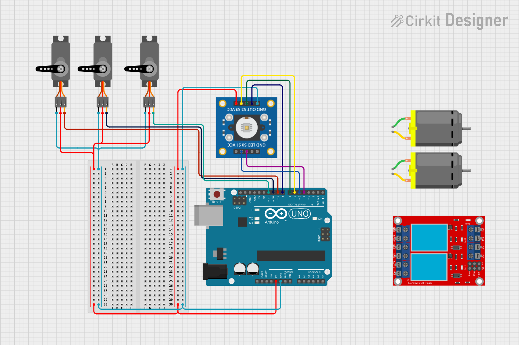
Arduino UNO Controlled Servo Array with TCS3200 Color Sensing

Circuit Documentation
Summary of the Circuit
This circuit is designed to interface an Arduino UNO with a color sensor (tcs3200) and control multiple servo motors based on the color sensor's output. The Arduino UNO serves as the central processing unit, reading the color sensor data and sending control signals to the servo motors. The color sensor can detect the color of an object, and the servo motors can be used to perform actions such as positioning or rotating parts of a machine or robot. The circuit is powered by the Arduino UNO's 5V output, which is distributed to the servo motors and the color sensor. Ground connections are also centralized through the Arduino UNO.
Component List
Arduino UNO
- Microcontroller board based on the ATmega328P
- Provides I/O pins for interfacing with various sensors and actuators
- Includes power supply pins (3.3V, 5V) and multiple ground (GND) pins
tcs3200 Color Sensor
- Color sensor module capable of detecting a wide range of colors
- Includes control pins (S0-S3) for setting the sensor's scaling frequency
- Output pin (OUT) provides a frequency corresponding to the detected color
Servo Motors
- Three servo motors capable of precise angular positioning
- Each servo has three pins: Power (VCC), Ground (GND), and Control (PWM)
DC Motors
- Two DC motors for rotational motion
- Each motor has two pins for power connection
2 Channel Relay Module
- Relay module with two channels for controlling high power devices
- Includes normally open (N.O.), common (COM), and normally closed (N.C.) terminals for each channel
- Control pins (IN 1, IN 2) for activating the relays
Wiring Details
Arduino UNO
- 5V pin connected to the VCC pins of all servo motors and the tcs3200 color sensor
- GND pin connected to the GND pins of all servo motors and the tcs3200 color sensor
- Digital pins D4-D8 used to interface with the tcs3200 color sensor and control the servo motors
tcs3200 Color Sensor
- VCC connected to 5V from the Arduino UNO
- GND connected to GND on the Arduino UNO
- OUT connected to digital pin D8 on the Arduino UNO
- S0-S3 control pins connected to digital pins D4-D7 on the Arduino UNO
Servo Motors
- VCC connected to 5V from the Arduino UNO
- GND connected to GND on the Arduino UNO
- PWM pins connected to digital pins D9-D11 on the Arduino UNO (one servo per pin)
DC Motors
- Not directly connected in the provided net list
2 Channel Relay Module
- Not directly connected in the provided net list
Documented Code
Arduino UNO Code (sketch.ino)
void setup() {
  // put your setup code here, to run once:

}

void loop() {
  // put your main code here, to run repeatedly:

}
Note: The provided code is a template and does not include specific functionality. It needs to be completed with setup configurations for the pins and the main logic to interact with the tcs3200 color sensor and control the servo motors based on the sensor's output.