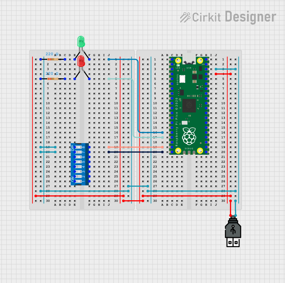
Raspberry Pi Pico Controlled Alternating LED Indicator

Circuit Documentation
Summary of the Circuit
This circuit is designed around the Raspberry Pi Pico microcontroller and includes a USB power input, two LEDs (one green and one red), two resistors, and an 8-position DIP switch. The Raspberry Pi Pico is programmed to alternately turn on the red and green LEDs in a blinking pattern. The USB power supply provides the necessary power for the circuit, while the resistors limit the current to the LEDs to prevent damage. The DIP switch is included in the design but is not utilized in the current code.
Component List
Raspberry Pi Pico
- Description: A microcontroller board based on the RP2040 microcontroller chip.
- Purpose: Acts as the central processing unit of the circuit, controlling the LEDs.
Resistor (220 Ohms)
- Description: A passive two-terminal electrical component that implements electrical resistance as a circuit element.
- Purpose: Limits the current flowing through the LEDs to prevent them from burning out.
LED: Two Pin (green)
- Description: A two-pin light-emitting diode that emits green light when powered.
- Purpose: Acts as an indicator light in the circuit.
LED: Two Pin (red)
- Description: A two-pin light-emitting diode that emits red light when powered.
- Purpose: Acts as an indicator light in the circuit.
USB power
- Description: A power supply module that provides power through a USB connection.
- Purpose: Supplies electrical power to the circuit.
DIP Switch (8 Position)
- Description: An array of simple mechanical switches packaged in a standard dual in-line package.
- Purpose: Provides a manual way to control the electrical connections in a circuit.
Wiring Details
Raspberry Pi Pico
- Pin 37 is connected to the positive (+) terminal of the USB power supply.
- Pin 38 is connected to the negative (-) terminal of the USB power supply and the first pins of both 220 Ohm resistors.
- Pin 16 is connected to the anode of the green LED.
- Pin 17 is connected to the anode of the red LED.
- Pins 19 and 20 are connected to pins 8 and 7 of the DIP switch, respectively.
Resistor (220 Ohms)
- One end of each resistor is connected to the negative (-) terminal of the USB power supply.
- The other end of one resistor is connected to the cathode of the green LED.
- The other end of the other resistor is connected to the cathode of the red LED.
LED: Two Pin (green)
- The anode is connected to pin 16 of the Raspberry Pi Pico.
- The cathode is connected to one of the 220 Ohm resistors.
LED: Two Pin (red)
- The anode is connected to pin 17 of the Raspberry Pi Pico.
- The cathode is connected to the other 220 Ohm resistor.
USB power
- The positive (+) terminal is connected to pin 37 of the Raspberry Pi Pico.
- The negative (-) terminal is connected to pin 38 of the Raspberry Pi Pico and the first pins of both 220 Ohm resistors.
DIP Switch (8 Position)
- Pin 8 is connected to pin 19 of the Raspberry Pi Pico.
- Pin 7 is connected to pin 20 of the Raspberry Pi Pico.
Documented Code
// Define the GPIO pins for the LEDs
const int redLEDPin = 17;   // GPIO pin connected to the anode of the red LED
const int greenLEDPin = 16; // GPIO pin connected to the anode of the green LED

void setup() {
  // Initialize the GPIO pins as outputs
  pinMode(redLEDPin, OUTPUT);
  pinMode(greenLEDPin, OUTPUT);
}

void loop() {
  // Turn on the red LED and turn off the green LED
  digitalWrite(redLEDPin, HIGH);
  digitalWrite(greenLEDPin, LOW);
  delay(1000); // Wait for 1 second

  // Turn off the red LED and turn on the green LED
  digitalWrite(redLEDPin, LOW);
  digitalWrite(greenLEDPin, HIGH);
  delay(1000); // Wait for 1 second
}
The code is written for the Arduino IDE and is intended to be uploaded to the Raspberry Pi Pico. It sets up two GPIO pins as outputs for the red and green LEDs. In the main loop, it alternates between turning the red LED on and the green LED off, then the red LED off and the green LED on, with a one-second delay between the states.