
Arduino UNO-Based Automated Temperature-Controlled Stirring System with RTC and Relay Module
View and Edit Project In Cirkit Designer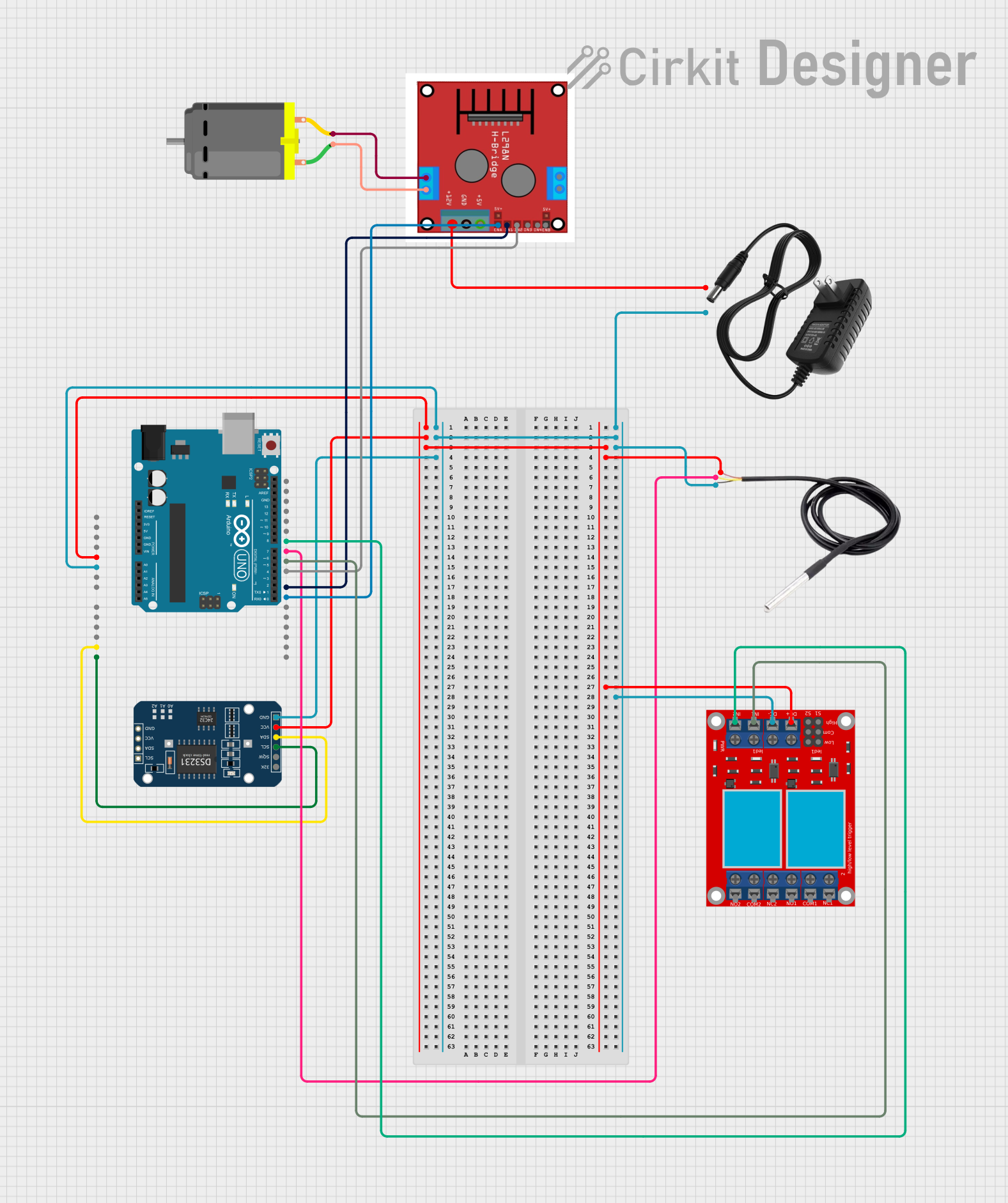
Circuit Documentation
Summary
This circuit involves an Arduino UNO microcontroller interfacing with various components including a DS3231 RTC module, a DS18B20 temperature sensor, a 2-channel relay module, a motor driver (L298N), a DC motor, and a 12V power supply. The Arduino UNO controls the relay module and motor driver based on the temperature readings from the DS18B20 and the time from the DS3231 RTC module.
Component List
Arduino UNO
- Description: A microcontroller board based on the ATmega328P.
- Pins: UNUSED, IOREF, Reset, 3.3V, 5V, GND, Vin, A0, A1, A2, A3, A4, A5, SCL, SDA, AREF, D13, D12, D11, D10, D9, D8, D7, D6, D5, D4, D3, D2, D1, D0
2-channel relay module
- Description: A module with two relays for switching high-power devices.
- Pins: N.O. 2, COM 2, N.C. 2, N.O. 1, COM 1, N.C. 1, pin 7, pin 8, pin 9, pin 10, pin 11, pin 12, VCC+, VCC- (GND), IN 1, IN 2
Motor Driver (L298N)
- Description: A dual H-bridge motor driver module.
- Pins: OUT 1, OUT 2, OUT 3, OUT 4, +12V INPUT, GND, +5V OUTPUT, ENA, IN 1, IN 2, IN 3, IN 4, ENB
DC Motor
- Description: A simple DC motor.
- Pins: pin 1, pin 2
12V power supply
- Description: A power supply providing 12V DC.
- Pins: +, -
DS18B20
- Description: A digital temperature sensor.
- Pins: signal, GND, vcc
DS3231 RTC
- Description: A real-time clock module.
- Pins: 32K, SQW, SCL, SDA, VCC, GND
Wiring Details
Arduino UNO
5V connected to:
- DS3231 RTC (VCC)
- DS18B20 (vcc)
- 2-channel relay module (VCC+)
GND connected to:
- DS3231 RTC (GND)
- 12V power supply (-)
- DS18B20 (GND)
- 2-channel relay module (VCC- (GND))
A4 connected to:
- DS3231 RTC (SDA)
A5 connected to:
- DS3231 RTC (SCL)
D11 connected to:
- 2-channel relay module (IN 2)
D10 connected to:
- DS18B20 (signal)
D9 connected to:
- 2-channel relay module (IN 1)
D8 connected to:
- Motor Driver (L298N) (IN 2)
D7 connected to:
- Motor Driver (L298N) (IN 1)
D6 connected to:
- Motor Driver (L298N) (ENA)
2-channel relay module
VCC+ connected to:
- Arduino UNO (5V)
VCC- (GND) connected to:
- Arduino UNO (GND)
IN 1 connected to:
- Arduino UNO (D9)
IN 2 connected to:
- Arduino UNO (D11)
Motor Driver (L298N)
IN 1 connected to:
- Arduino UNO (D7)
IN 2 connected to:
- Arduino UNO (D8)
ENA connected to:
- Arduino UNO (D6)
OUT 1 connected to:
- DC Motor (pin 2)
OUT 2 connected to:
- DC Motor (pin 1)
+12V INPUT connected to:
- 12V power supply (+)
DC Motor
pin 1 connected to:
- Motor Driver (L298N) (OUT 2)
pin 2 connected to:
- Motor Driver (L298N) (OUT 1)
12V power supply
+ connected to:
- Motor Driver (L298N) (+12V INPUT)
- connected to:
- Arduino UNO (GND)
DS18B20
signal connected to:
- Arduino UNO (D10)
GND connected to:
- Arduino UNO (GND)
vcc connected to:
- Arduino UNO (5V)
DS3231 RTC
SDA connected to:
- Arduino UNO (A4)
SCL connected to:
- Arduino UNO (A5)
VCC connected to:
- Arduino UNO (5V)
GND connected to:
- Arduino UNO (GND)
Code Documentation
#include <Wire.h>
#include <RTClib.h>
#include <OneWire.h>
#include <DallasTemperature.h>

// RTC-module instellen
RTC_DS3231 rtc;

// DS18B20 instellen
#define ONE_WIRE_BUS 2 // Data-pin van de DS18B20
OneWire oneWire(ONE_WIRE_BUS);
DallasTemperature sensors(&oneWire);

// Pin-definities
#define RELAY1_PIN 9 // Relais 1
#define RELAY2_PIN 10 // Relais 2
#define MOTOR_IN1 7 // Motor IN1
#define MOTOR_IN2 8 // Motor IN2
#define MOTOR_ENA 6 // Motor EN-A (PWM)

// Tijdconfiguratie
const int stirringStartHour = 9;   // Starttijd roeren (uur)
const int stirringStartMinute = 0; // Starttijd roeren (minuut)
const int stirringDuration = 10;   // Roertijd in seconden
const int stirringInterval = 20;   // Tijd tussen roeracties in seconden

void setup() {
  // Seriële monitor starten
  Serial.begin(9600);

  // RTC-module starten
  if (!rtc.begin()) {
    Serial.println("RTC-module niet gevonden!");
    while (1);
  }

  // Controleer of de RTC correct werkt
  if (rtc.lostPower()) {
    Serial.println("RTC-module verloor stroom, instellen op huidige tijd...");
    rtc.adjust(DateTime(F(__DATE__), F(__TIME__))); // Stelt de tijd in op compilatietijd
  }

  // DS18B20 starten
  sensors.begin();

  // Pin-modi instellen
  pinMode(RELAY1_PIN, OUTPUT);
  pinMode(RELAY2_PIN, OUTPUT);
  pinMode(MOTOR_IN1, OUTPUT);
  pinMode(MOTOR_IN2, OUTPUT);
  pinMode(MOTOR_ENA, OUTPUT);

  // Relais en motor uitschakelen bij start
  digitalWrite(RELAY1_PIN, LOW);
  digitalWrite(RELAY2_PIN, LOW);
  stopMotor();
}

void loop() {
  // Huidige tijd ophalen
  DateTime now = rtc.now();

  // Roeren op ingestelde tijden
  if (now.hour() == stirringStartHour && now.minute() == stirringStartMinute) {
    Serial.println("Roeren gestart...");
    startMotor(150); // Motor starten op 150 (PWM-snelheid)
    delay(stirringDuration * 1000); // Roeren gedurende de ingestelde tijd
    stopMotor();
    delay(stirringInterval * 1000); // Wacht tot de volgende roeractie
  }

  // Temperatuur meten
  sensors.requestTemperatures();
  float temperature = sensors.getTempCByIndex(0);
  Serial.print("Temperatuur: ");
  Serial.print(temperature);
  Serial.println(" °C");

  // Relaisbesturing voorbeeld
  if (temperature > 50.0) { // Als temperatuur hoger is dan 50 °C
    digitalWrite(RELAY1_PIN, HIGH); // Zet apparaat A aan
  } else {
    digitalWrite(RELAY1_PIN, LOW); // Zet apparaat A uit
  }

  delay(1000); // Wacht 1 seconde voor herhaling
}

// Functie om de motor te starten
void startMotor(int speed) {
  analogWrite(MOTOR_ENA, speed); // Stel snelheid in
  digitalWrite(MOTOR_IN1, HIGH);
  digitalWrite(MOTOR_IN2, LOW);
}

// Functie om de motor te stoppen
void stopMotor() {
  digitalWrite(MOTOR_IN1, LOW);
  digitalWrite(MOTOR_IN2, LOW);
  analogWrite(MOTOR_ENA, 0);
}
This code initializes the RTC and temperature sensor, sets up the pin modes, and contains the main loop that reads the current time and