Arduino and ESP32 Controlled Automated Irrigation System with Soil Moisture Monitoring and LCD Display
Circuit Documentation
Summary
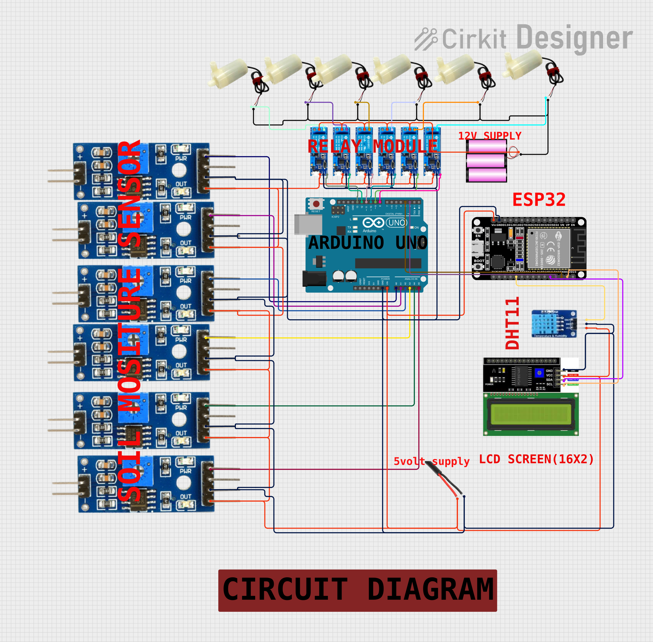
This circuit is designed to monitor soil moisture levels using multiple Soil Moisture Modules and control water pumps accordingly to maintain optimal soil conditions. The system uses an Arduino UNO as the main microcontroller to read analog values from the Soil Moisture Modules and trigger Relay Modules that control the water pumps. An ESP32 microcontroller is used for additional connectivity and sensor integration, such as the DHT11 temperature and humidity sensor. An LCD I2C Display provides a user interface for displaying sensor data. The circuit is powered by a 12V battery, and an AC Wire is included, likely for power distribution purposes.
Component List
- Soil Moisture Modules: Used to measure the moisture level in the soil.
- AC Wire: Used for power distribution within the circuit.
- Relay Modules (5v-30v): Used to control the power to the water pumps based on the soil moisture readings.
- Arduino UNO: Acts as the central microcontroller for reading sensor data and controlling the relay modules.
- LCD I2C Display: Displays information such as soil moisture levels and temperature/humidity readings.
- 5v Mini Water Pumps: Used to pump water into the soil when the moisture level is below a certain threshold.
- Battery (12V): Provides power to the circuit.
- ESP32 (30 Pin): Provides additional processing power and connectivity options.
- DHT11: Measures temperature and humidity of the environment.
Wiring Details
Soil Moisture Modules
- Analog Pin: Connected to the Arduino UNO's analog input pins (A0, A1, A2, A3, A4, A5) for reading moisture levels.
- Digital Pin: Not used in this circuit.
- VCC Pin: Connected to the positive voltage rail.
- Ground Pin: Connected to the ground rail.
AC Wire
- GND: Connected to the ground rail.
- Phase: Connected to the positive voltage rail.
Relay Modules (5v-30v)
- Common Contact: Connected to the positive terminal of the 12V battery.
- Normally Open: Connected to the positive pins of the 5v mini water pumps.
- Normally Closed: Not used in this circuit.
- Trigger: Connected to the digital output pins on the Arduino UNO (D8, D9, D10, D11, D12, D13).
- V-: Connected to the ground rail.
- V+: Connected to the positive voltage rail.
Arduino UNO
- Analog Pins (A0-A5): Connected to the analog pins of the Soil Moisture Modules.
- Digital Pins (D8-D13): Connected to the trigger pins of the Relay Modules.
- GND: Connected to the ground rail.
- Vin: Connected to the positive voltage rail.
LCD I2C Display
- SDA: Connected to the ESP32's D21 pin.
- SCL: Connected to the ESP32's D22 pin.
- VCC: Connected to the positive voltage rail.
- GND: Connected to the ground rail.
5v Mini Water Pumps
- Positive Pin: Connected to the normally open contacts of the Relay Modules.
- Negative Pin: Connected to the negative terminal of the 12V battery.
Battery (12V)
- + (Positive Terminal): Connected to the common contacts of the Relay Modules.
- - (Negative Terminal): Connected to the negative pins of the 5v mini water pumps.
ESP32 (30 Pin)
- TX0: Connected to the Arduino UNO's D3 pin.
- RX0: Connected to the Arduino UNO's D2 pin.
- GND: Connected to the ground rail.
- Vin: Connected to the positive voltage rail.
- D21 (SDA): Connected to the SDA pin of the LCD I2C Display.
- D22 (SCL): Connected to the SCL pin of the LCD I2C Display.
- D4: Connected to the DATA pin of the DHT11 sensor.
DHT11
- DATA: Connected to the D4 pin of the ESP32.
- VCC: Connected to the positive voltage rail.
- GND: Connected to the ground rail.
Documented Code
Arduino UNO Code (sketch.ino)
void setup() {
  // put your setup code here, to run once:

}

void loop() {
  // put your main code here, to run repeatedly:

}
ESP32 Code
No code provided for the ESP32 microcontroller.
Note: The provided code for the Arduino UNO is a template with no functional implementation. To complete the documentation, the actual code implementing the logic for reading sensors and controlling the relays should be provided.