
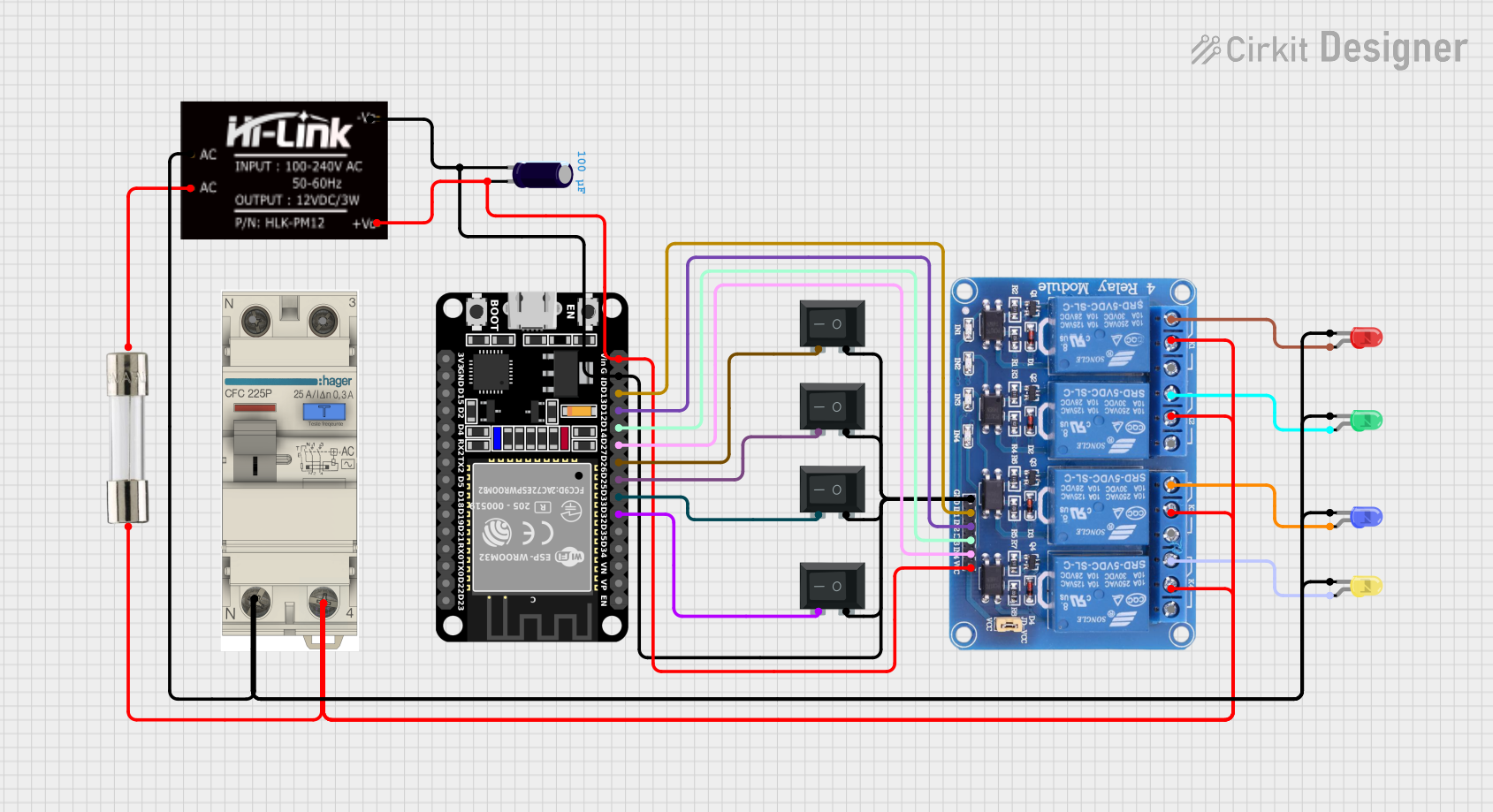
Circuit Documentation
Summary
This document provides a detailed overview of a circuit that includes a 4-channel relay module, multiple rocker switches, LEDs of various colors, an ESP32 microcontroller, an AC circuit breaker, a fuse, an HLK-PM12 power module, and an electrolytic capacitor. The circuit is designed to control the relays using the ESP32, with the relays in turn controlling the LEDs. The rocker switches are used to provide manual control inputs to the ESP32.
Component List
Relay 4 Channel 5v
- Description: A relay module with 4 channels, each capable of switching high voltage devices.
- Pins: GND, IN1, IN2, IN3, IN4, VCC, COM1, COM2, COM3, COM4, NO1, NO2, NO3, NO4, NC1, NC2, NC3, NC4
Rocker Switch (SPST)
- Description: Single Pole Single Throw (SPST) rocker switch.
- Pins: 1, 2
LED: Two Pin (blue)
- Description: Blue LED with two pins.
- Pins: cathode, anode
LED: Two Pin (green)
- Description: Green LED with two pins.
- Pins: cathode, anode
LED: Two Pin (red)
- Description: Red LED with two pins.
- Pins: cathode, anode
LED: Two Pin (yellow)
- Description: Yellow LED with two pins.
- Pins: cathode, anode
ESP32 (30 pin)
- Description: ESP32 microcontroller with 30 pins.
- Pins: EN, VP, VN, D34, D35, D32, D33, D25, D26, D27, D14, D12, D13, GND, Vin, D23, D22, TX0, RX0, D21, D19, D18, D5, TX2, RX2, D4, D2, D15, 3V3
AC Circuit Breaker
- Description: AC circuit breaker for overcurrent protection.
- Pins: GND, VOUT, VIN
Fuse
- Description: Fuse for overcurrent protection.
- Pins: Terminal 1, Terminal 2
HLK-PM12
- Description: Power module for converting AC to DC.
- Pins: +V0, -V0, AC
Electrolytic Capacitor
- Description: Capacitor with a capacitance of 0.0001 Farads.
- Pins: -, +
Wiring Details
Relay 4 Channel 5v
GND is connected to:
- GND of ESP32
- -V0 of HLK-PM12
- Pin 1 of all Rocker Switches
-
- pin of Electrolytic Capacitor
VCC is connected to:
- +V0 of HLK-PM12
- Vin of ESP32
-
- pin of Electrolytic Capacitor
IN1 is connected to D13 of ESP32
IN2 is connected to D12 of ESP32
IN3 is connected to D14 of ESP32
IN4 is connected to D27 of ESP32
COM1, COM2, COM3, COM4 are connected to VOUT of AC Circuit Breaker and Terminal 1 of Fuse
NC1 is connected to anode of Red LED
NC2 is connected to anode of Green LED
NC3 is connected to anode of Blue LED
NC4 is connected to anode of Yellow LED
Rocker Switch (SPST)
Pin 1 is connected to:
- GND of ESP32
- -V0 of HLK-PM12
- GND of Relay 4 Channel 5v
-
- pin of Electrolytic Capacitor
Pin 2 is connected to:
- D26 of ESP32
- D25 of ESP32
- D32 of ESP32
- D33 of ESP32
LED: Two Pin (blue)
- cathode is connected to AC of HLK-PM12 and GND of AC Circuit Breaker
- anode is connected to NC3 of Relay 4 Channel 5v
LED: Two Pin (green)
- cathode is connected to AC of HLK-PM12 and GND of AC Circuit Breaker
- anode is connected to NC2 of Relay 4 Channel 5v
LED: Two Pin (red)
- cathode is connected to AC of HLK-PM12 and GND of AC Circuit Breaker
- anode is connected to NC1 of Relay 4 Channel 5v
LED: Two Pin (yellow)
- cathode is connected to AC of HLK-PM12 and GND of AC Circuit Breaker
- anode is connected to NC4 of Relay 4 Channel 5v
ESP32 (30 pin)
GND is connected to:
- GND of Relay 4 Channel 5v
- -V0 of HLK-PM12
- Pin 1 of all Rocker Switches
-
- pin of Electrolytic Capacitor
Vin is connected to:
- +V0 of HLK-PM12
- VCC of Relay 4 Channel 5v
-
- pin of Electrolytic Capacitor
D13 is connected to IN1 of Relay 4 Channel 5v
D12 is connected to IN2 of Relay 4 Channel 5v
D14 is connected to IN3 of Relay 4 Channel 5v
D27 is connected to IN4 of Relay 4 Channel 5v
D26 is connected to Pin 2 of Rocker Switch
D25 is connected to Pin 2 of Rocker Switch
D32 is connected to Pin 2 of Rocker Switch
D33 is connected to Pin 2 of Rocker Switch
AC Circuit Breaker
GND is connected to:
- cathode of Blue LED
- cathode of Green LED
- cathode of Yellow LED
- cathode of Red LED
- AC of HLK-PM12
VOUT is connected to:
- COM1, COM2, COM3, COM4 of Relay 4 Channel 5v
- Terminal 1 of Fuse
Fuse
- Terminal 1 is connected to VOUT of AC Circuit Breaker and COM1, COM2, COM3, COM4 of Relay 4 Channel 5v
- Terminal 2 is connected to AC of HLK-PM12
HLK-PM12
+V0 is connected to:
- Vin of ESP32
- VCC of Relay 4 Channel 5v
-
- pin of Electrolytic Capacitor
-V0 is connected to:
- GND of ESP32
- GND of Relay 4 Channel 5v
- Pin 1 of all Rocker Switches
-
- pin of Electrolytic Capacitor
AC is connected to:
- cathode of Blue LED
- cathode of Green LED
- cathode of Yellow LED
- cathode of Red LED
- GND of AC Circuit Breaker
- Terminal 2 of Fuse
Electrolytic Capacitor
- is connected to:
- GND of ESP32
- GND of Relay 4 Channel 5v
- -V0 of HLK-PM12
- Pin 1 of all Rocker Switches
+ is connected to:
- Vin of ESP32
- VCC of Relay 4 Channel 5v
- +V0 of HLK-PM12
Code
No code is provided for this circuit.