
Arduino UNO Controlled Relay with LCD Interface and Keypad Input
View and Edit Project In Cirkit Designer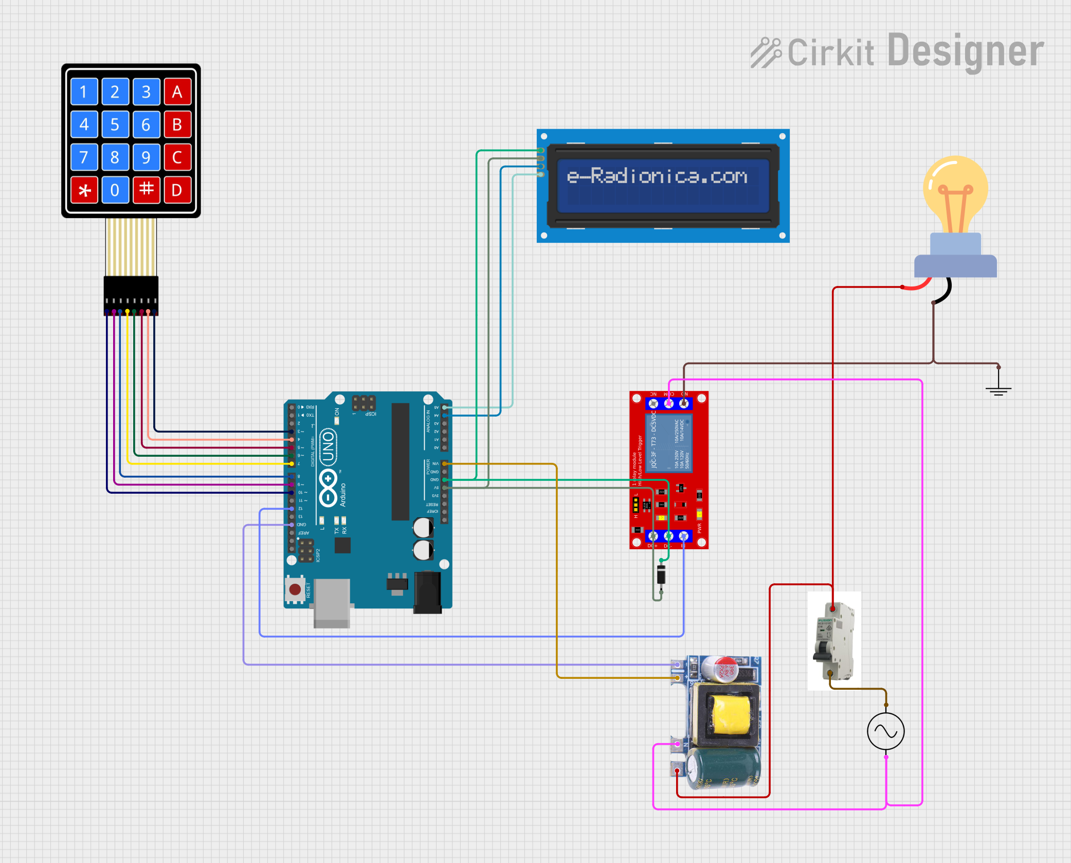
Circuit Documentation
Summary
This circuit integrates an Arduino UNO microcontroller with a 4x4 membrane matrix keypad, an LCD screen with I2C interface, a 1-channel 5V relay module, and an LED bulb for AC control. The circuit is powered by a mini AC-DC converter module that steps down mains voltage to 5V. A diode is used for protection in the power supply circuit. The relay module controls the LED bulb, and the keypad provides user input to the Arduino, which in turn displays information on the LCD screen.
Component List
Arduino UNO
- Microcontroller board based on the ATmega328P
- Provides digital I/O pins, analog inputs, and various power outputs
4X4 Membrane Matrix Keypad
- Provides a 4x4 matrix of buttons for user input
- Each row and column is connected to a digital pin on the Arduino
LCD screen 16x2 I2C
- Alphanumeric liquid crystal display with 16 characters by 2 lines
- Uses I2C communication to interface with the Arduino
1 Channel 5V Relay Module
- Electromechanical switch with one normally open (N.O.) contact
- Controlled by an Arduino digital output
Diode
- Semiconductor device that allows current to flow in one direction only
- Used for protecting the circuit from reverse voltage
LED bulb AC / Bombillo AC
- Light-emitting diode bulb designed for AC power
- Controlled by the relay module
Mini AC-DC 110V-230V to 5V 700mA Module
- Power supply module that converts AC mains voltage to 5V DC
- Powers the Arduino and other 5V components
Ac Supply
- Provides the mains voltage to the circuit
- Connected to the AC-DC converter and the relay module for controlling the LED bulb
MCB (Miniature Circuit Breaker)
- Safety device that automatically switches off electrical circuit during an overload or short circuit
- Protects the AC supply line
Wiring Details
Arduino UNO
5VandGNDare connected to the power bus for 5V and ground distribution.Vinis connected to the 5V output from the mini AC-DC converter module.A4 (SDA)andA5 (SCL)are connected to the I2C data and clock lines of the LCD screen.D12controls the relay module input.D10,D9,D8,D7,D6,D5,D4,D3are connected to the rows and columns of the 4x4 keypad.
4X4 Membrane Matrix Keypad
- Rows
R1toR4are connected to Arduino pinsD10toD7. - Columns
C1toC4are connected to Arduino pinsD6toD3.
LCD screen 16x2 I2C
VCCandGNDare connected to the 5V and ground power bus.SDAandSCLare connected to the Arduino'sA4andA5pins.
1 Channel 5V Relay Module
VCC+andVCC- (GND)are connected to the 5V and ground power bus.INis controlled by the Arduino'sD12pin.N.O.is connected to the LED bulb andCOMis connected to the neutral line from the AC supply.
Diode
Anodeis connected to the 5V power bus.Cathodeis connected to the ground power bus.
LED bulb AC / Bombillo AC
+is connected to the MCB'sOUT.-is connected to the relay module'sN.O.contact.
Mini AC-DC 110V-230V to 5V 700mA Module
5voutput is connected to the Arduino'sVin.GNDis connected to the ground power bus.NeutralandLifeare connected to the AC supply and MCB.
Ac Supply
+veis connected to the MCB'sIN.-veis connected to the neutral line of the AC-DC converter module and the relay module'sCOM.
MCB
INis connected to the AC supply's+ve.OUTis connected to the LED bulb and the AC-DC converter module'sLife.
Documented Code
void setup() {
  // put your setup code here, to run once:

}

void loop() {
  // put your main code here, to run repeatedly:

}
The provided code is a template with empty setup() and loop() functions, which are the entry points for Arduino sketches. The setup() function is called once when the sketch starts and is used for initializing settings, while the loop() function runs repeatedly, allowing the microcontroller to perform operations based on input or time-based events. Additional code would be required to handle the keypad input, control the relay, and update the LCD display.