ESP32-Based Ambient Light Sensor with BH1750

Circuit Documentation
Summary of the Circuit
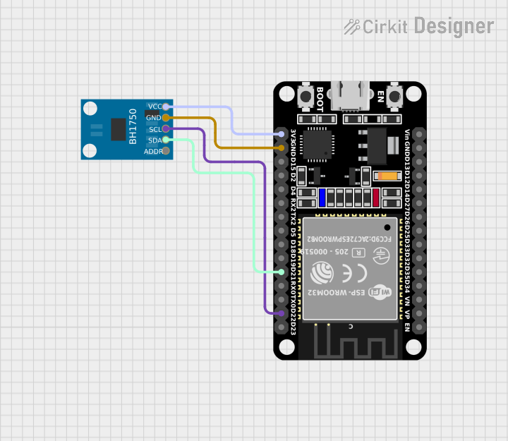
This circuit consists of an ESP32 microcontroller and a BH1750 light sensor module. The ESP32 is a versatile microcontroller with Wi-Fi and Bluetooth capabilities, and it is used here as the central processing unit of the circuit. The BH1750 is an I2C digital light sensor that provides ambient light intensity measurements. The ESP32 communicates with the BH1750 sensor over the I2C bus to read light intensity data.
Component List
ESP32 (30 pin)
- Description: A 30-pin microcontroller with Wi-Fi and Bluetooth capabilities.
- Purpose: Acts as the central processing unit and communicates with the BH1750 light sensor.
- Pins: EN, VP, VN, D34, D35, D32, D33, D25, D26, D27, D14, D12, D13, GND, Vin, D23, D22, TX0, RX0, D21, D19, D18, D5, TX2, RX2, D4, D2, D15, 3V3.
BH1750
- Description: A digital light sensor module that measures ambient light intensity.
- Purpose: Provides ambient light intensity data to the ESP32.
- Pins: VCC, GND, SCL, SDA, ADDR.
Wiring Details
ESP32 (30 pin)
- D22 - Connected to the SCL pin of the BH1750 for I2C clock signal.
- D21 - Connected to the SDA pin of the BH1750 for I2C data signal.
- GND - Connected to the GND pin of the BH1750 to establish a common ground.
- 3V3 - Connected to the VCC pin of the BH1750 to provide power to the sensor.
BH1750
- VCC - Connected to the 3V3 pin of the ESP32 for power supply.
- GND - Connected to the GND pin of the ESP32 to establish a common ground.
- SCL - Connected to the D22 pin of the ESP32 for I2C clock signal.
- SDA - Connected to the D21 pin of the ESP32 for I2C data signal.
- ADDR - Not connected (no net specified).
Documented Code
There is no code provided for the microcontroller in this circuit. To fully utilize the ESP32 and BH1750, embedded code is required to initialize the I2C communication, read sensor data, and process the information accordingly. The code would typically include setup routines, a main loop, and I2C communication functions. Since no code is provided, this section cannot be documented further.