
Raspberry Pi Pico-Based Smart Fan Controller with Touchscreen Interface
View and Edit Project In Cirkit Designer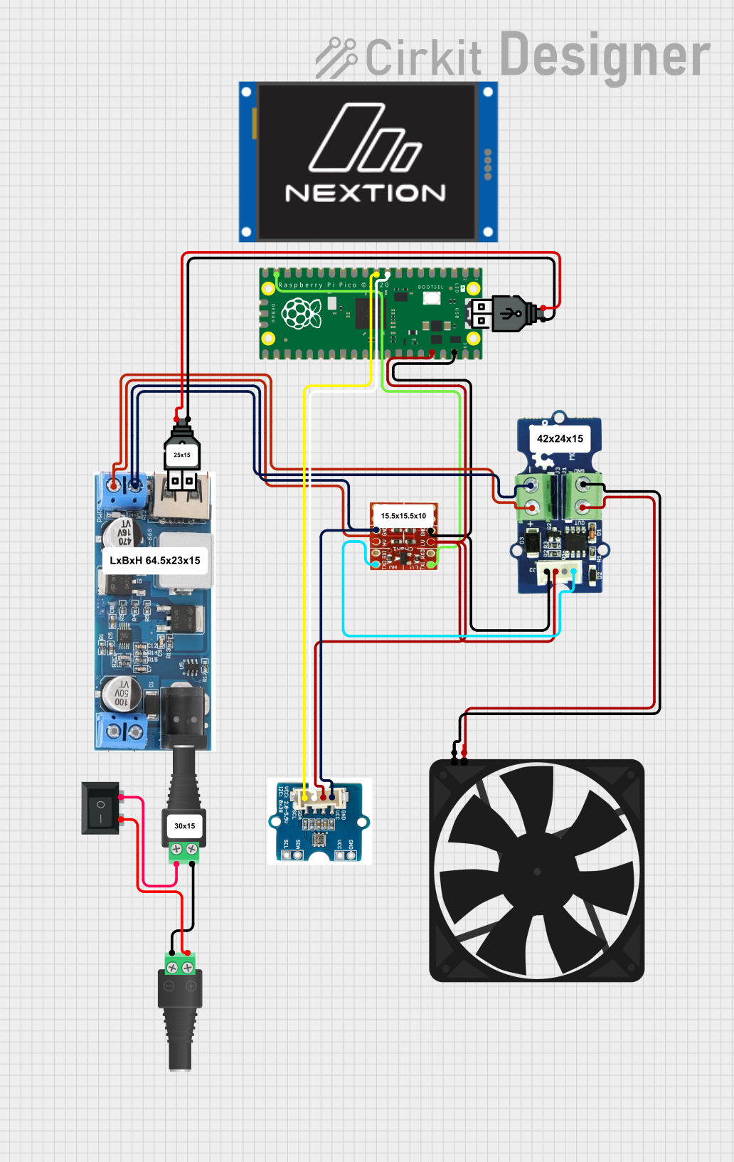
Circuit Documentation
Summary
This document provides a detailed overview of a circuit designed to control a fan using a Raspberry Pi Pico microcontroller. The circuit includes various components such as a DC-DC converter, a MOSFET, a rocker switch, a sensor, and an LCD display. The Raspberry Pi Pico is programmed to manage the fan speed based on temperature readings from the AHT20 sensor and user inputs from the LCD touch screen.
Component List
Fan
- Description: A simple fan used for cooling.
- Pins: GND, 5V
DCDC 12V/5V 3A
- Description: A DC-DC converter that steps down 12V to 5V.
- Pins: 12V (+), GND, 5V (+), Vin (+), Vin (-)
Seeed Mosfet CJQ4435
- Description: A MOSFET used for switching the fan.
- Pins: 5V (+), GND (-), OUT (+), OUT(-), Schwarz, Rot, Weiss, Gelb
Rocker Switch (SPST)
- Description: A single-pole single-throw switch.
- Pins: 1, 2
Raspberry Pi Pico
- Description: A microcontroller used to control the circuit.
- Pins: pin 1 to pin 43
2.1mm Barrel Jack with Terminal Block
- Description: A barrel jack for power input.
- Pins: POS, NEG
USB power
- Description: USB power input.
- Pins: +, -
Logic Level Converter 3.3V 5V TTL
- Description: A logic level converter for interfacing 3.3V and 5V logic.
- Pins: GND (Raspi), GP14 (Raspi), 3.3V (Raspi), Mosfet Gelb, 5V (+), 5V (-)
AHT20 Sensor
- Description: A temperature and humidity sensor.
- Pins: Schwarz, Rot, Weiss, Gelb
Nextion Touch LCD 2.4"
- Description: A touch LCD display.
- Pins: VCC, GND, RX, TX
Wiring Details
Fan
- 5V connected to OUT (+) of Seeed Mosfet CJQ4435
- GND connected to OUT(-) of Seeed Mosfet CJQ4435
DCDC 12V/5V 3A
- 5V (+) connected to 5V (+) of Logic Level Converter 3.3V 5V TTL and Seeed Mosfet CJQ4435
- GND connected to 5V (-) of Logic Level Converter 3.3V 5V TTL, GND (-) of Seeed Mosfet CJQ4435, and Schwarz of AHT20 Sensor
Seeed Mosfet CJQ4435
- 5V (+) connected to 5V (+) of DCDC 12V/5V 3A and Logic Level Converter 3.3V 5V TTL
- GND (-) connected to GND of DCDC 12V/5V 3A and 5V (-) of Logic Level Converter 3.3V 5V TTL
- OUT (+) connected to 5V of Fan
- OUT(-) connected to GND of Fan
- Schwarz connected to pin 38 of Raspberry Pi Pico and GND (Raspi) of Logic Level Converter 3.3V 5V TTL
- Rot connected to pin 36 of Raspberry Pi Pico, Rot of AHT20 Sensor, and 3.3V (Raspi) of Logic Level Converter 3.3V 5V TTL
- Weiss connected to pin 9 of Raspberry Pi Pico and Weiss of AHT20 Sensor
- Gelb connected to Mosfet Gelb of Logic Level Converter 3.3V 5V TTL
Rocker Switch (SPST)
- 1 connected to POS of 2.1mm Barrel Jack with Terminal Block
- 2 connected to POS of another 2.1mm Barrel Jack with Terminal Block
Raspberry Pi Pico
- pin 38 connected to Schwarz of Seeed Mosfet CJQ4435 and GND (Raspi) of Logic Level Converter 3.3V 5V TTL
- pin 36 connected to Rot of AHT20 Sensor, Rot of Seeed Mosfet CJQ4435, and 3.3V (Raspi) of Logic Level Converter 3.3V 5V TTL
- pin 9 connected to Weiss of AHT20 Sensor
- pin 10 connected to Gelb of AHT20 Sensor
- pin 19 connected to GP14 (Raspi) of Logic Level Converter 3.3V 5V TTL
2.1mm Barrel Jack with Terminal Block
- POS connected to 1 of Rocker Switch (SPST)
- NEG connected to NEG of another 2.1mm Barrel Jack with Terminal Block
USB power
- + connected to + of another USB power
- - connected to - of another USB power
Logic Level Converter 3.3V 5V TTL
- 5V (+) connected to 5V (+) of DCDC 12V/5V 3A and Seeed Mosfet CJQ4435
- 5V (-) connected to GND of DCDC 12V/5V 3A, GND (-) of Seeed Mosfet CJQ4435, and Schwarz of AHT20 Sensor
- GND (Raspi) connected to pin 38 of Raspberry Pi Pico and Schwarz of Seeed Mosfet CJQ4435
- GP14 (Raspi) connected to pin 19 of Raspberry Pi Pico
- 3.3V (Raspi) connected to pin 36 of Raspberry Pi Pico, Rot of AHT20 Sensor, and Rot of Seeed Mosfet CJQ4435
- Mosfet Gelb connected to Gelb of Seeed Mosfet CJQ4435
AHT20 Sensor
- Schwarz connected to 5V (-) of Logic Level Converter 3.3V 5V TTL, GND of DCDC 12V/5V 3A, and GND (-) of Seeed Mosfet CJQ4435
- Rot connected to pin 36 of Raspberry Pi Pico, 3.3V (Raspi) of Logic Level Converter 3.3V 5V TTL, and Rot of Seeed Mosfet CJQ4435
- Weiss connected to pin 9 of Raspberry Pi Pico
- Gelb connected to pin 10 of Raspberry Pi Pico
Documented Code
Arduino Sketch (C++)
void setup() {
  // put your setup code here, to run once:

}

void loop() {
  // put your main code here, to run repeatedly:

}
MicroPython Code
import time  # Importiert das time-Modul zur Handhabung von Zeitfunktionen
time.sleep(0.1)

from machine import Pin, I2C, SPI, PWM  # Importiert die notwendigen Module Pin, SPI und PWM aus der machine-Bibliothek
import framebuf  # Importiert das framebuf-Modul, das für die Displaypuffer-Verwaltung zuständig ist

import os  # Importiert das os-Modul zur Handhabung von Betriebssystemfunktionen (wird in diesem Skript nicht verwendet)
#import time


# Definiert die Pins für das LCD-Display und das Touchpanel
LCD_DC   = 8
LCD_CS   = 9
LCD_SCK  = 10
LCD_MOSI = 11
LCD_MISO = 12
LCD_BL   = 13
LCD_RST  = 15
TP_CS    = 16
TP_IRQ   = 17
luefter_pwm_pin = 14 #Lüfter = GPIO15 (Pin 20)
buzzer_pin = 2


# Definition von Variablen
temperatur_soll=20
temperatur_ist=0
#ventilator_soll=0
luefterlast=100