
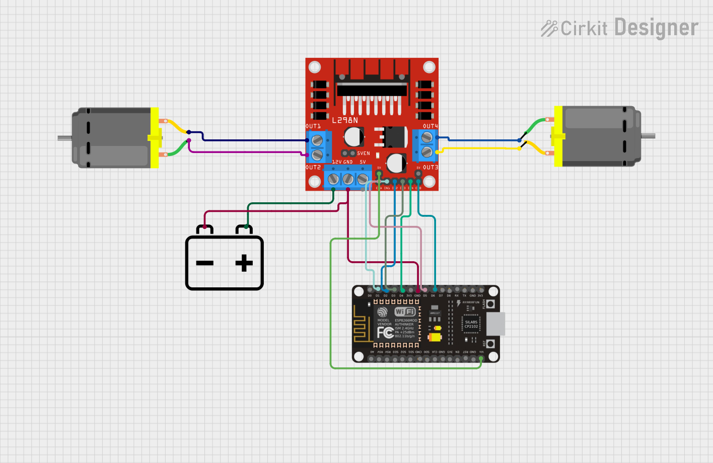
Circuit Documentation
Summary of the Circuit
This circuit is designed to control two DC motors using an ESP8266 NodeMCU microcontroller and an L298N DC motor driver. The motors are powered by a 12V battery, and the microcontroller is responsible for sending control signals to the motor driver, which in turn controls the direction and speed of the motors.
Component List
DC Motor
- Description: A standard DC motor used for converting electrical energy into mechanical motion.
- Pins:
- pin 1: Motor terminal
- pin 2: Motor terminal
L298N DC Motor Driver
- Description: A motor driver module capable of driving two DC motors or one stepper motor.
- Pins:
- OUT1, OUT2, OUT3, OUT4: Output pins connected to the DC motors
- 12V: Power supply input for motor voltage
- GND: Ground connection
- 5V: Logic power supply
- ENA, ENB: Enable pins for motor control
- IN1, IN2, IN3, IN4: Input pins for motor control signals
12V Battery
- Description: A power source for the circuit, providing the necessary voltage to drive the DC motors.
- Pins:
- +: Positive terminal
- -: Negative terminal
ESP8266 NodeMCU
- Description: A microcontroller board with Wi-Fi capability, used for controlling the motor driver.
- Pins:
- D0-D8: Digital I/O pins
- RX, TX: UART communication pins
- A0: Analog input pin
- 3V3: 3.3V power output
- GND: Ground connection
- VIN: Voltage input for the board
Wiring Details
DC Motor 1
- pin 1: Connected to OUT2 on the L298N DC motor driver
- pin 2: Connected to OUT1 on the L298N DC motor driver
DC Motor 2
- pin 1: Connected to OUT4 on the L298N DC motor driver
- pin 2: Connected to OUT3 on the L298N DC motor driver
L298N DC Motor Driver
- OUT1, OUT2: Connected to DC Motor 1
- OUT3, OUT4: Connected to DC Motor 2
- 12V: Connected to the + terminal of the 12V Battery
- GND: Connected to the GND pin of the ESP8266 NodeMCU and the - terminal of the 12V Battery
- ENA, ENB: Connected to D5 and D6 pins of the ESP8266 NodeMCU respectively
- IN1, IN2, IN3, IN4: Connected to D1, D2, D3, and D4 pins of the ESP8266 NodeMCU respectively
- +5V-J1: Connected to the VIN pin of the ESP8266 NodeMCU
12V Battery
- +: Connected to the 12V pin of the L298N DC motor driver
- -: Connected to the GND pin of the L298N DC motor driver
ESP8266 NodeMCU
- D1: Connected to IN1 on the L298N DC motor driver
- D2: Connected to IN2 on the L298N DC motor driver
- D3: Connected to IN3 on the L298N DC motor driver
- D4: Connected to IN4 on the L298N DC motor driver
- D5: Connected to ENA on the L298N DC motor driver
- D6: Connected to ENB on the L298N DC motor driver
- GND: Connected to the GND pin of the L298N DC motor driver
- VIN: Connected to the +5V-J1 pin of the L298N DC motor driver
Documented Code
Since no code was provided in the input, this section is left blank. Normally, this section would include the source code for the microcontroller, with comments explaining the functionality of each part of the code. The code would typically initialize the hardware peripherals, set up the Wi-Fi connection if needed, and contain the main control loop for sending signals to the motor driver to control the motors.