
Circuit Documentation
Summary of the Circuit
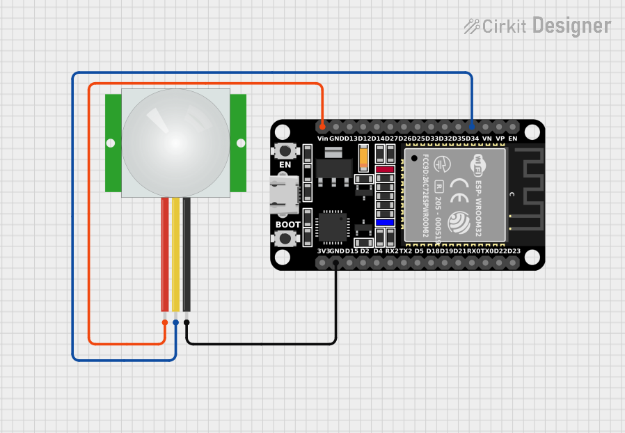
This circuit integrates an ESP32 microcontroller with a PIR (Passive Infrared) sensor. The ESP32 is a versatile microcontroller with Wi-Fi and Bluetooth capabilities, and it is used here to process the signal from the PIR sensor, which detects motion based on changes in infrared levels. The PIR sensor outputs a signal when motion is detected, which is then read by one of the digital pins on the ESP32. The ESP32 is powered through its Vin pin, and both the ESP32 and the PIR sensor share a common ground.
Component List
ESP32 (30 pin)
- Description: A 30-pin microcontroller with Wi-Fi and Bluetooth capabilities.
- Pins: EN, VP, VN, D34, D35, D32, D33, D25, D26, D27, D14, D12, D13, GND, Vin, D23, D22, TX0, RX0, D21, D19, D18, D5, TX2, RX2, D4, D2, D15, 3V3
- Purpose: To process the signal from the PIR sensor and perform actions based on motion detection.
PIR Sensor
- Description: A motion sensor that detects changes in infrared radiation.
- Pins: VDD, SIG, GND
- Purpose: To detect motion and send a corresponding signal to the ESP32.
Wiring Details
ESP32 (30 pin)
- D34: Connected to the SIG pin of the PIR sensor to receive motion detection signals.
- Vin: Connected to the VDD pin of the PIR sensor to provide power.
- GND: Connected to the GND pin of the PIR sensor to establish a common ground.
PIR Sensor
- SIG: Connected to the D34 pin of the ESP32 to send motion detection signals.
- VDD: Connected to the Vin pin of the ESP32 to receive power.
- GND: Connected to the GND pin of the ESP32 to establish a common ground.
Documented Code
There is no code provided for the microcontroller in this circuit. If code is later provided, it should be documented here with explanations of how the ESP32 is programmed to handle the signal from the PIR sensor, including setup, loop, and any interrupt service routines or functions used to process the motion detection.