
Circuit Documentation
Summary
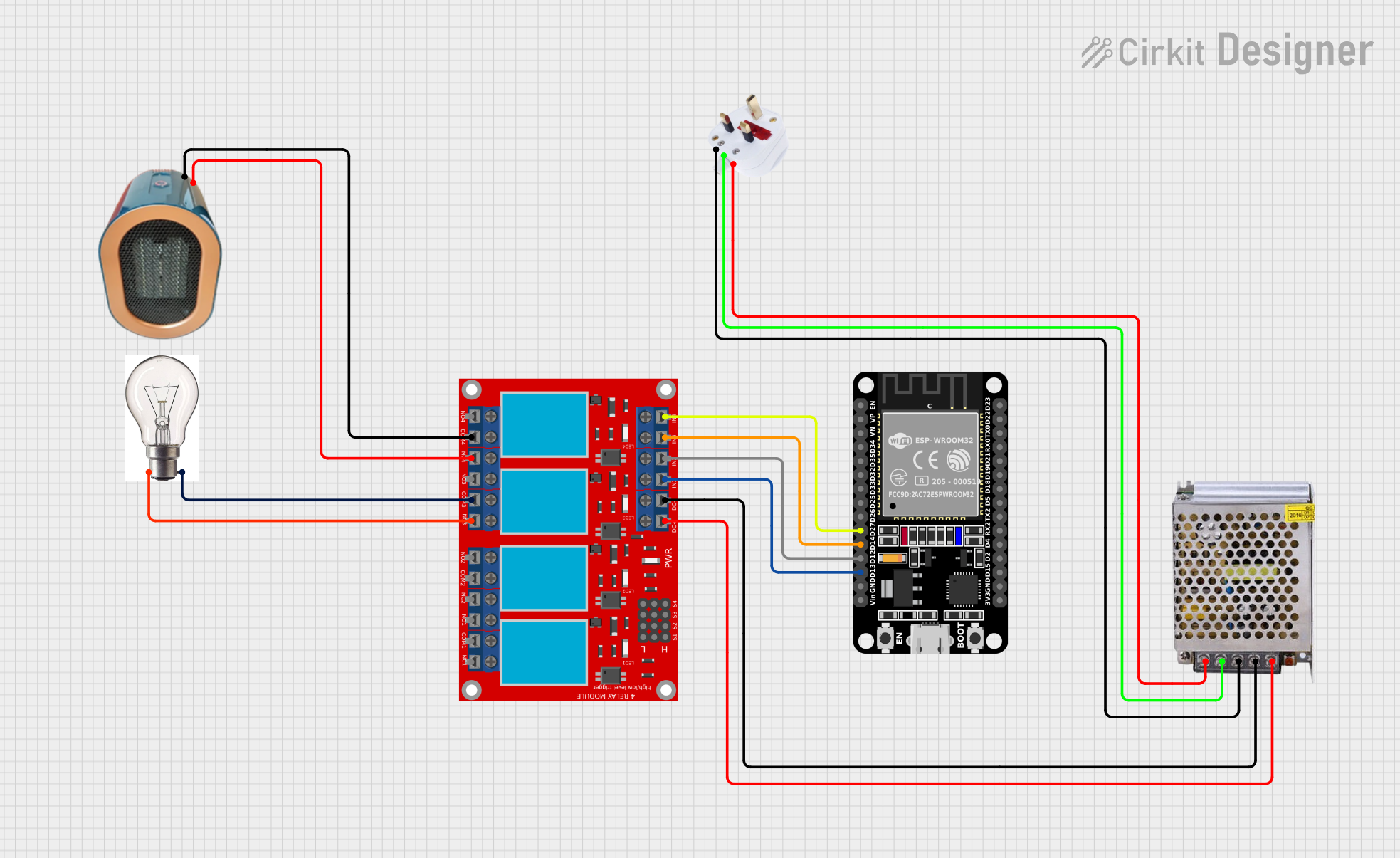
The circuit described in the provided inputs is designed to control a heater and a bulb using an ESP32 microcontroller and a 4-channel relay module. The ESP32 is responsible for sending control signals to the relay module, which in turn switches the heater and the bulb on or off. The power supply unit (PSU) provides the necessary DC voltage to power the relay module and the ESP32. The PSU is also connected to a plug that supplies AC voltage to the PSU.
Component List
ESP32 (30 pin)
- Description: A microcontroller with Wi-Fi and Bluetooth capabilities, featuring a wide range of GPIO pins.
- Purpose: Acts as the central control unit for the circuit, sending signals to the relay module to control the connected devices.
4 Channel Relay Module
- Description: A module with four relays that can be individually controlled to switch connected devices on or off.
- Purpose: Receives control signals from the ESP32 to switch the heater and bulb.
Heater
- Description: A heating element that can be switched on or off.
- Purpose: Provides heat when powered.
POWER SUPPLY 12V 5AMP
- Description: A power supply unit that converts AC voltage to 12V DC voltage.
- Purpose: Powers the relay module and the ESP32.
Bulb
- Description: An electric light source.
- Purpose: Provides illumination when powered.
Plug
- Description: An electrical connector that connects the power supply to the AC mains.
- Purpose: Supplies AC voltage to the power supply unit.
Wiring Details
ESP32 (30 pin)
- D27 connected to Relay Module IN 4
- D14 connected to Relay Module IN 3
- D12 connected to Relay Module IN 2
- D13 connected to Relay Module IN 1
4 Channel Relay Module
- IN 1, IN 2, IN 3, IN 4 connected to ESP32 D13, D12, D14, D27 respectively
- COM 4 connected to Heater (-)
- N.C. 4 connected to Heater (+)
- COM 3 connected to Bulb (-VE)
- N.C. 3 connected to Bulb (+VE)
- VCC+ connected to POWER SUPPLY 12V-24V Output (DC)
- VCC- (GND) connected to POWER SUPPLY GND (DC)
Heater
- (+) connected to Relay Module N.C. 4
- (-) connected to Relay Module COM 4
POWER SUPPLY 12V 5AMP
- 12V-24V Output (DC) connected to Relay Module VCC+
- GND (DC) connected to Relay Module VCC- (GND)
- 220V Positive Pole (AC) connected to Plug (+)
- 220V Negative Pole (AC) connected to Plug (-)
- GND connected to Plug GND
Bulb
- (+VE) connected to Relay Module N.C. 3
- (-VE) connected to Relay Module COM 3
Plug
- (+) connected to POWER SUPPLY 220V Positive Pole (AC)
- (-) connected to POWER SUPPLY 220V Negative Pole (AC)
- GND connected to POWER SUPPLY GND
Documented Code
No code was provided for the microcontroller. The ESP32 is expected to be programmed to control the relay module based on the application's requirements. The code would typically initialize the GPIO pins connected to the relay module, set up Wi-Fi or Bluetooth communication if necessary, and implement the logic for when to activate each relay to control the heater and the bulb.