
ESP32-Controlled Multi-Display Interactive System with Pushbutton Inputs
View and Edit Project In Cirkit Designer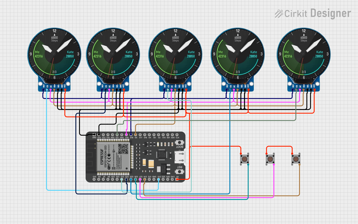
Circuit Documentation
Summary of the Circuit
This circuit appears to be designed to interface multiple GC9A01 display modules with an ESP32 microcontroller. The ESP32 is a versatile microcontroller with WiFi and Bluetooth capabilities, and it is being used to control the displays and read inputs from pushbuttons. The GC9A01 is a round LCD display module that requires digital control signals for operation. The pushbuttons are likely used to provide user input to the system.
Component List
Microcontroller
- ESP32 - 38 pins: A microcontroller with WiFi and Bluetooth capabilities, featuring a wide range of GPIO pins for interfacing with various peripherals.
Display Modules
- GC9A01: A round LCD display module that requires digital control signals such as reset (RST), chip select (CS), data/command (DC), serial data (SDA), and serial clock (SCL) for operation.
Pushbuttons
- Pushbutton: A simple switch mechanism for control of a machine or process. In this circuit, it is likely used for user input.
Wiring Details
ESP32 - 38 pins
- G18: Connected to the RST pin of all GC9A01 display modules for resetting the displays.
- G13: Connected to the CS pin of one GC9A01 display module.
- G19: Connected to the DC pin of all GC9A01 display modules for data/command selection.
- G5: Connected to the SDA pin of all GC9A01 display modules for serial data communication.
- G23: Connected to the SCL pin of all GC9A01 display modules for serial clock signal.
- GND: Connected to the GND pin of all GC9A01 display modules and pushbuttons for a common ground reference.
- 5V: Connected to the VCC pin of all GC9A01 display modules for power supply.
- G25, G33, G32, G21: Connected to the CS pin of individual GC9A01 display modules for chip select functionality.
- G26, G27, G14: Connected to the Pin 4 (out) of individual pushbuttons for reading button states.
GC9A01 Display Modules
- RST: Connected to G18 on the ESP32 for resetting the display.
- CS: Connected to individual GPIOs (G13, G25, G33, G32, G21) on the ESP32 for chip select functionality.
- DC: Connected to G19 on the ESP32 for data/command selection.
- SDA: Connected to G5 on the ESP32 for serial data communication.
- SCL: Connected to G23 on the ESP32 for serial clock signal.
- GND: Connected to GND on the ESP32 for a common ground reference.
- VCC: Connected to 5V on the ESP32 for power supply.
Pushbuttons
- Pin 1 (in): Connected to VCC for power supply and to other pushbuttons for shared functionality.
- Pin 4 (out): Connected to individual GPIOs (G26, G27, G14) on the ESP32 for reading button states.
Documented Code
No code has been provided for the microcontroller. Typically, the code would initialize the GPIO pins, set up communication protocols (e.g., SPI for the displays), and include the logic for reading button presses and updating the display content accordingly.
Please note that without the actual code and a more detailed description of the circuit's intended functionality, the above documentation is based on standard practices and assumptions about the connections and components used.