Arduino UNO Based GPS and GSM Tracking System with Emergency Alert Feature
Circuit Documentation
Summary
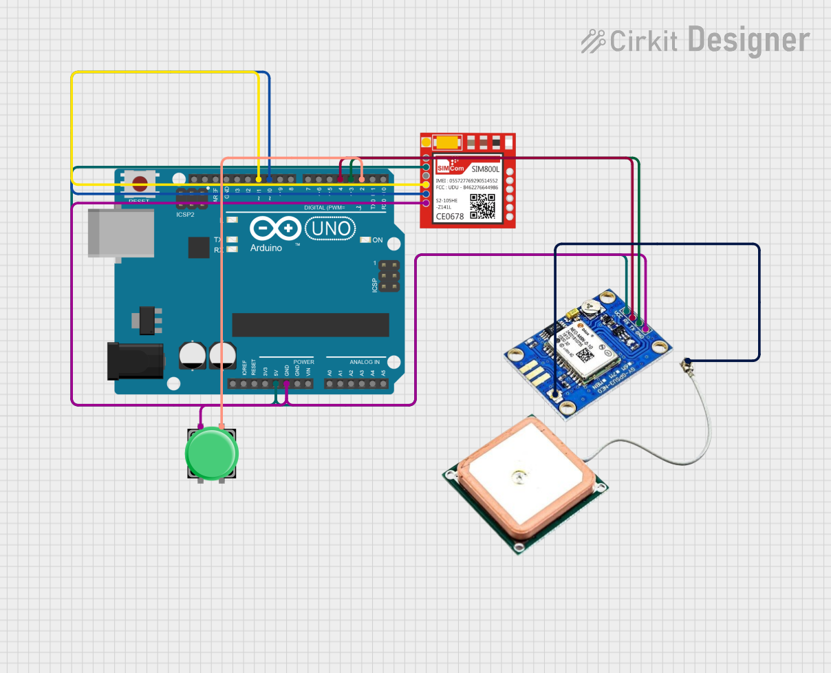
This circuit integrates an Arduino UNO microcontroller with a SIM800L GSM module and a Ublox NEO-M8N GPS module to create a system capable of GPS tracking and GSM communication. An emergency pushbutton is also included to trigger alerts. The Arduino UNO is responsible for controlling the flow of data between the GPS and GSM modules, processing GPS data, and handling the logic for emergency alerting and communication with a remote server.
Component List
Arduino UNO
- Description: A microcontroller board based on the ATmega328P.
- Purpose: Acts as the central processing unit for the circuit, interfacing with the GPS and GSM modules, reading the pushbutton state, and executing the embedded code.
Sim800l GSM Module
- Description: A GSM/GPRS module that allows cellular communication including SMS and data transmission.
- Purpose: Used for sending SMS alerts, making calls, and sending GPS data to a remote server via GPRS.
Ublox NEO-M8N GPS Module
- Description: A high-performance GPS module with a built-in antenna.
- Purpose: Provides accurate location data which is processed by the Arduino and sent out via the GSM module.
Pushbutton
- Description: A simple pushbutton switch.
- Purpose: Serves as an emergency button that, when pressed, triggers an alert through the GSM module.
Wiring Details
Arduino UNO
- 5V: Powers the Sim800l GSM module and Ublox NEO-M8N GPS module.
- GND: Common ground for the circuit.
- D11: Connected to RXD of the Sim800l GSM module for serial communication.
- D10: Connected to TXD of the Sim800l GSM module for serial communication.
- D4: Connected to RX of the Ublox NEO-M8N GPS module for serial communication.
- D3: Connected to TX of the Ublox NEO-M8N GPS module for serial communication.
- D2: Connected to one of the pushbutton pins for detecting button presses.
Sim800l GSM Module
- VCC: Powered by the 5V output from the Arduino UNO.
- GND: Connected to the common ground.
- RXD: Receives data from D11 of the Arduino UNO.
- TXD: Transmits data to D10 of the Arduino UNO.
Ublox NEO-M8N GPS Module
- VCC: Powered by the 5V output from the Arduino UNO.
- GND: Connected to the common ground.
- RX: Receives data from D4 of the Arduino UNO.
- TX: Transmits data to D3 of the Arduino UNO.
- RF coaxial cable connectors: Antenna connection for receiving GPS signals.
Pushbutton
- Pin 1: Connected to the common ground.
- Pin 3: Connected to D2 of the Arduino UNO to detect button presses.
Documented Code
#include <SoftwareSerial.h>
#include <TinyGPS++.h>

// Pin configurations for GSM and GPS modules
SoftwareSerial gsmSerial(10, 11);  // RX, TX for GSM module
SoftwareSerial gpsSerial(3, 4);    // RX, TX for GPS module

TinyGPSPlus gps;

// Pin configuration for emergency button
const int buttonPin = 2;  // Emergency button pin

// Server URL for sending data
const char* serverURL = "https://cuboid-rigorous-red.glitch.me/"; // Replace with your server URL

bool buttonPressed = false;

void setup() {
  pinMode(buttonPin, INPUT_PULLUP);   // Configure button pin as input with pull-up resistor
  gsmSerial.begin(9600);              // Initialize GSM serial communication
  gpsSerial.begin(9600);              // Initialize GPS serial communication
  Serial.begin(9600);                 // Start the serial monitor for debugging

  // Send SMS to confirm system startup
  sendSMS("System started. GPS tracking enabled.");
}

void loop() {
  // Process incoming GPS data
  while (gpsSerial.available() > 0) {
    gps.encode(gpsSerial.read());

    // Check if new GPS location is available
    if (gps.location.isUpdated()) {
      float latitude = gps.location.lat();
      float longitude = gps.location.lng();
      Serial.print("Latitude= "); Serial.print(latitude, 6);
      Serial.print(" Longitude= "); Serial.println(longitude, 6);

      // Send the location to the server
      sendLocationToServer(latitude, longitude);
    }
  }

  // Check if the emergency button is pressed
  if (digitalRead(buttonPin) == LOW) {
    buttonPressed = true;
    delay(200);  // Debounce delay
  }

  if (buttonPressed) {
    // Trigger emergency alert
    sendEmergencyAlert();
    buttonPressed = false;  // Reset button pressed flag
  }
}

// Function to send GPS location to the server
void sendLocationToServer(float lat, float lng) {
  String postData = "lat=" + String(lat, 6) + "&lng=" + String(lng, 6);
  sendHTTPPostRequest("/update-location", postData);
}

// Function to trigger an emergency alert
void sendEmergencyAlert() {
  // Send alert message
  sendSMS("Emergency! Sending location to contacts.");

  // Call predefined contact (example number)
  makeCall("+918454044438");

  // Send alert to server
  String postData = "";
  sendHTTPPostRequest("/alert", postData);
}

// Function to send SMS using GSM module
void sendSMS(String message) {
  gsmSerial.println("AT+CMGF=1");    // Set SMS mode to text
  delay(1000);
  gsmSerial.println("AT+CMGS=\"+918454044438\"");  // Replace with predefined emergency contact
  delay(1000);
  gsmSerial.print(message);
  delay(1000);
  gsmSerial.write(26);  // Send CTRL+Z to indicate the end of the message
  delay(5000);
}

// Function to make a call using GSM module
void makeCall(String phoneNumber) {
  gsmSerial.println("ATD" + phoneNumber + ";");  // Dial the phone number
  delay(10000);  // Wait for 10 seconds
  gsmSerial.println("ATH");  // Hang up the call
}

// Function to send an HTTP POST request to the server
void sendHTTPPostRequest(String endpoint, String postData) {
  gsmSerial.println("AT+CGATT=1");  // Attach to GPRS network
  delay(1000);
  gsmSerial.println("AT+CGDCONT=1,\"IP\",\"your-apn\"");  // Set APN (replace with your APN)
  delay(1000);
  gsmSerial.println("AT+CGACT=1,1");  // Activate GPRS context
  delay(1000);

  gsmSerial.println("AT+HTTPINIT");  // Initialize HTTP service
  delay(1000);
  gsmSerial.println("AT+HTTPPARA=\"URL\",\"" + String(serverURL) + endpoint + "\"");  // Set URL
  delay(1000);
  gsmSerial.println("AT+HTTPPARA=\"CONTENT\",\"application/x-www-form-urlencoded\"");  // Set content type
  delay(1000);
  gsmSerial.println("AT+HTTPDATA=" + String(postData.length()) + ",10000");  // Set data length
  delay(1000);
  gsmSerial.print(postData);  // Send POST data
  delay(1000);
  gsmSerial.println("AT+HTTPACTION=1");  // Execute HTTP POST action
  delay(5000);
  gsmSerial.println("AT+HTTPTERM");  // Terminate HTTP service
  delay(1000);
}
Note: The code provided is for the Arduino UNO microcontroller and includes functionality for GPS data processing, emergency button handling, GSM communication for SMS and calls, and HTTP POST requests for server communication. The phone number and server URL are placeholders and should be replaced with actual contact details and server endpoints. Additionally, the APN settings in the sendHTTPPostRequest function should be configured according to the GSM network provider.