
Arduino-Controlled Robotic Vehicle with Color and IR Sensing
View and Edit Project In Cirkit Designer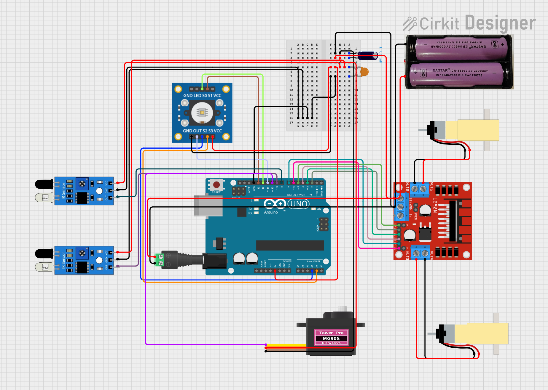
Circuit Documentation
Summary of the Circuit
This circuit is designed to control a pair of hobby gearmotors using an L298N DC motor driver, which is interfaced with an Arduino UNO microcontroller. The circuit includes sensors for input (IR sensors and a TCS3200 color sensor), a servo motor for additional actuation, and a power supply system that includes a 7.4V battery, a resettable fuse for protection, and an electrolytic capacitor for voltage smoothing. The Arduino UNO is the central processing unit that receives sensor inputs and controls the motors and servo based on the programmed logic.
Component List
Microcontroller
- Arduino UNO: A microcontroller board based on the ATmega328P, with a variety of digital and analog I/O pins.
Motor Driver
- L298N DC motor driver: A module capable of driving two DC motors or one stepper motor with current up to 2A per channel.
Motors
- Hobby Gearmotor with 48:1 gearbox: A DC motor with a gearbox for increased torque, used for driving mechanisms.
Sensors
- TCS3200 color sensor: A sensor that can detect the color of objects using an array of photodiodes with filters.
- IR sensor: An infrared sensor used for proximity or line detection.
Actuator
- Servomotor MG90S: A small and lightweight servo motor for precise angular movement.
Power Components
- 7.4V Battery: The main power source for the circuit.
- 2.1mm Barrel Jack with Terminal Block: A connector for attaching external power sources.
- Electrolytic Capacitor: Used for voltage smoothing and filtering.
- Resettable Fuse PTC: A protective component that limits current in case of an overload.
Wiring Details
Arduino UNO
- 5V and GND pins are used to power the IR sensors, TCS3200 color sensor, and the resettable fuse.
- Analog pins A3 and A4 are connected to the S2 and S3 pins of the TCS3200 color sensor, respectively.
- Digital pins D2 to D13 are used to interface with the L298N motor driver, TCS3200 color sensor, IR sensors, and the servo motor.
L298N DC Motor Driver
- 12V and GND pins are connected to the positive and negative terminals of the 7.4V battery, respectively, with the negative terminal also connected to the electrolytic capacitor.
- IN1 to IN4 pins are controlled by the Arduino digital pins D2 to D7 for motor direction control.
- ENA and ENB pins are connected to Arduino digital pins D5 and D6 for motor speed control via PWM.
- OUT1 to OUT4 pins are connected to the pins of the two hobby gearmotors.
Hobby Gearmotor with 48:1 Gearbox
- Each motor has two pins connected to the OUT1/OUT2 and OUT3/OUT4 of the L298N motor driver for bidirectional control.
TCS3200 Color Sensor
- VCC and GND are powered by the Arduino's 5V and GND.
- S0 to S3 pins are connected to Arduino digital pins D12 to D13 and analog pins A3 to A4 for frequency scaling and color selection.
- OUT pin is connected to Arduino digital pin D11 for frequency output.
IR Sensors
- VCC and GND pins are powered by the Arduino's 5V and GND.
- OUT pins are connected to Arduino digital pins D8 and D9 for digital signal output.
Servomotor MG90S
- VCC and GND are powered by the 7.4V battery.
- SIG pin is controlled by Arduino digital pin D10 for position control.
Electrolytic Capacitor
- The positive pin is connected to the 12V input of the L298N motor driver and the positive terminal of the 7.4V battery.
- The negative pin is connected to the ground plane of the circuit.
Resettable Fuse PTC
- One pin is connected to the 5V output of the Arduino.
- The other pin is connected to the VCC of the IR sensors and the TCS3200 color sensor.
2.1mm Barrel Jack with Terminal Block
- POS and NEG terminals are connected to the positive and negative terminals of the 7.4V battery, respectively.
Documented Code
Arduino UNO Code (sketch.ino)
void setup() {
  // put your setup code here, to run once:

}

void loop() {
  // put your main code here, to run repeatedly:

}
Note: The provided code is a template and does not contain any functional logic. It needs to be populated with the setup and loop functions to control the circuit components based on the desired behavior.