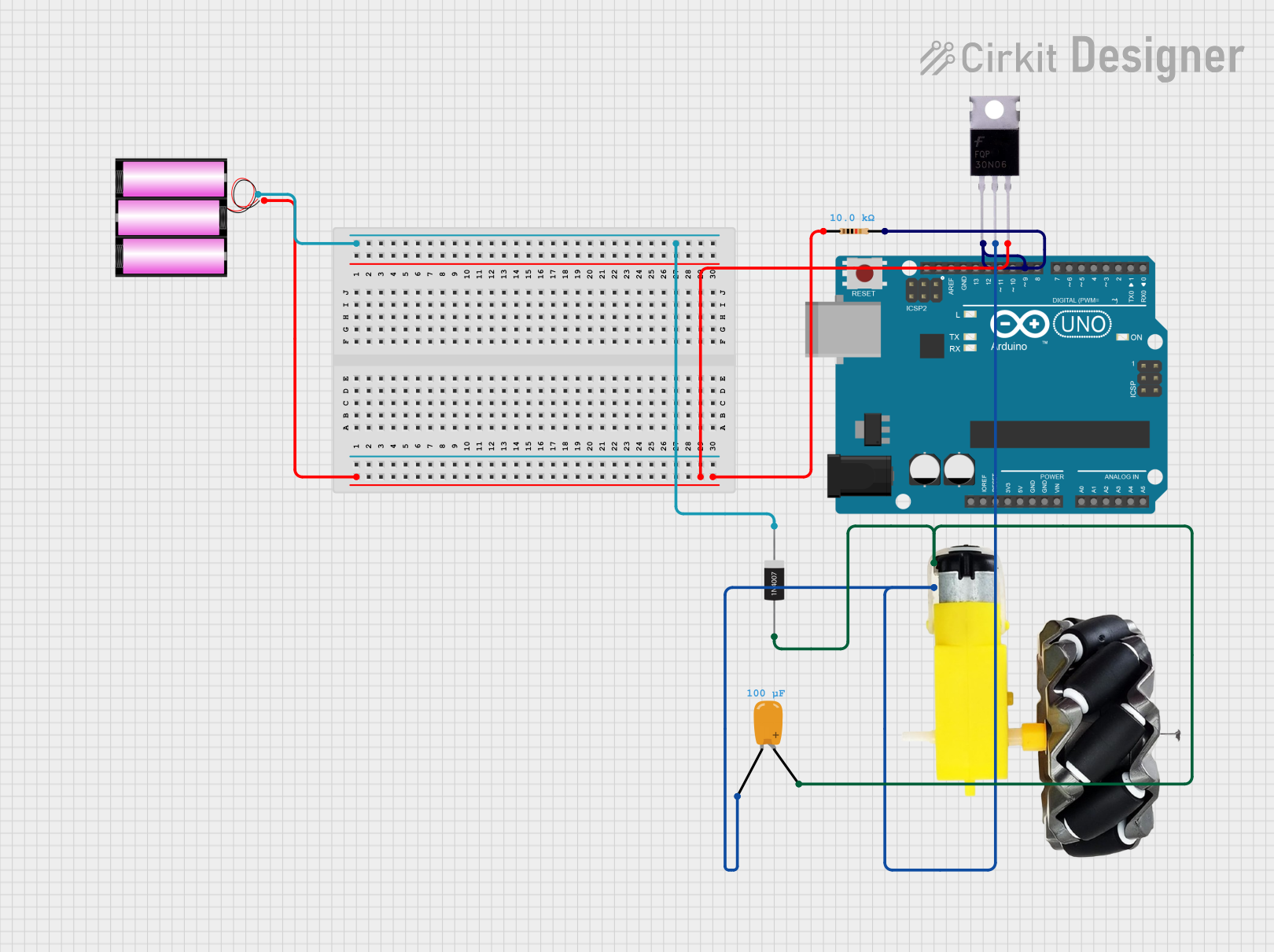
Arduino-Controlled PWM Motor Driver with MOSFET and Overvoltage Protection

Circuit Documentation
Summary of the Circuit
This circuit is designed to control a motor using an Arduino UNO microcontroller. The motor's speed is regulated through Pulse Width Modulation (PWM) on one of the Arduino's digital pins. A MOSFET is used as a switch to control the high-power circuit of the motor. A resistor is connected between the MOSFET gate and ground to ensure the MOSFET turns off when not driven by the Arduino. A diode is used to protect against voltage spikes caused by the inductive load of the motor, and a tantalum capacitor is added to smooth out any voltage fluctuations. The circuit is powered by a 12V battery.
Component List
Arduino UNO
- Microcontroller board based on the ATmega328P
- Pins: UNUSED, IOREF, Reset, 3.3V, 5V, GND, Vin, A0-A5, SCL, SDA, AREF, D13-D0
Resistor
- 10k Ohm resistor
- Pins: pin1, pin2
MOSFET
- Transistor used for switching electronic signals
- Pins: Gate, Drain, Source
Tantalum Capacitor
- 0.1 µF (100 nF) capacitance
- Pins: -, +
Motor and Wheels
- Electric motor with attached wheels
- Pins: vcc, GND
Battery 12V
- Power source for the circuit
- Pins: +, -
1N4007 Rectifier Diode
- Diode used for protecting the circuit from voltage spikes
- Pins: Cathode, Anode
Wiring Details
Arduino UNO
- D9 connected to the Gate of the MOSFET and pin2 of the Resistor
Resistor
- pin1 connected to the Source of the MOSFET
- pin2 connected to the Gate of the MOSFET and D9 of the Arduino UNO
MOSFET
- Gate connected to D9 of the Arduino UNO and pin2 of the Resistor
- Drain connected to the motor and wheels (vcc), the Anode of the 1N4007 Rectifier Diode, and the + of the Tantalum Capacitor
- Source connected to the - of the battery 12V and pin1 of the Resistor
Tantalum Capacitor
- connected to the GND of the motor and wheels
- connected to the vcc of the motor and wheels, the Anode of the 1N4007 Rectifier Diode, and the Drain of the MOSFET
Motor and Wheels
- GND connected to the - of the Tantalum Capacitor
- vcc connected to the Drain of the MOSFET, the Anode of the 1N4007 Rectifier Diode, and the + of the Tantalum Capacitor
Battery 12V
- connected to the Source of the MOSFET
- connected to the Cathode of the 1N4007 Rectifier Diode
1N4007 Rectifier Diode
- Cathode connected to the + of the battery 12V
- Anode connected to the vcc of the motor and wheels, the Drain of the MOSFET, and the + of the Tantalum Capacitor
Documented Code
/*
 * This Arduino sketch controls a motor using a MOSFET. The motor speed is
 * controlled via PWM on digital pin 9. A 10k ohm resistor is connected
 * between the gate pin and ground to ensure the MOSFET turns off when the
 * pin is low. A diode and capacitor are used to protect against voltage
 * spikes.
 */

const int motorPin = 9;

void setup() {
  pinMode(motorPin, OUTPUT);
}

void loop() {
  // Set the PWM frequency to 500 Hz
  analogWriteFrequency(motorPin, 500);

  // Set the PWM duty cycle to 50% (adjust this to control speed)
  analogWrite(motorPin, 128);

  // You can change the duty cycle in a loop to vary the speed
  // For example:
  for (int dutyCycle = 0; dutyCycle <= 255; dutyCycle++) {
    analogWrite(motorPin, dutyCycle);
    delay(10);
  }
}
The code sets up the Arduino to output a PWM signal on pin D9, which controls the MOSFET gate and thus the motor speed. The PWM frequency is set to 500 Hz, and the duty cycle starts at 50%. The loop then gradually increases the duty cycle from 0% to 100%, varying the motor speed accordingly.