
Arduino UNO Controlled 12V Relay System for Fan and Bulb with Battery Power
View and Edit Project In Cirkit Designer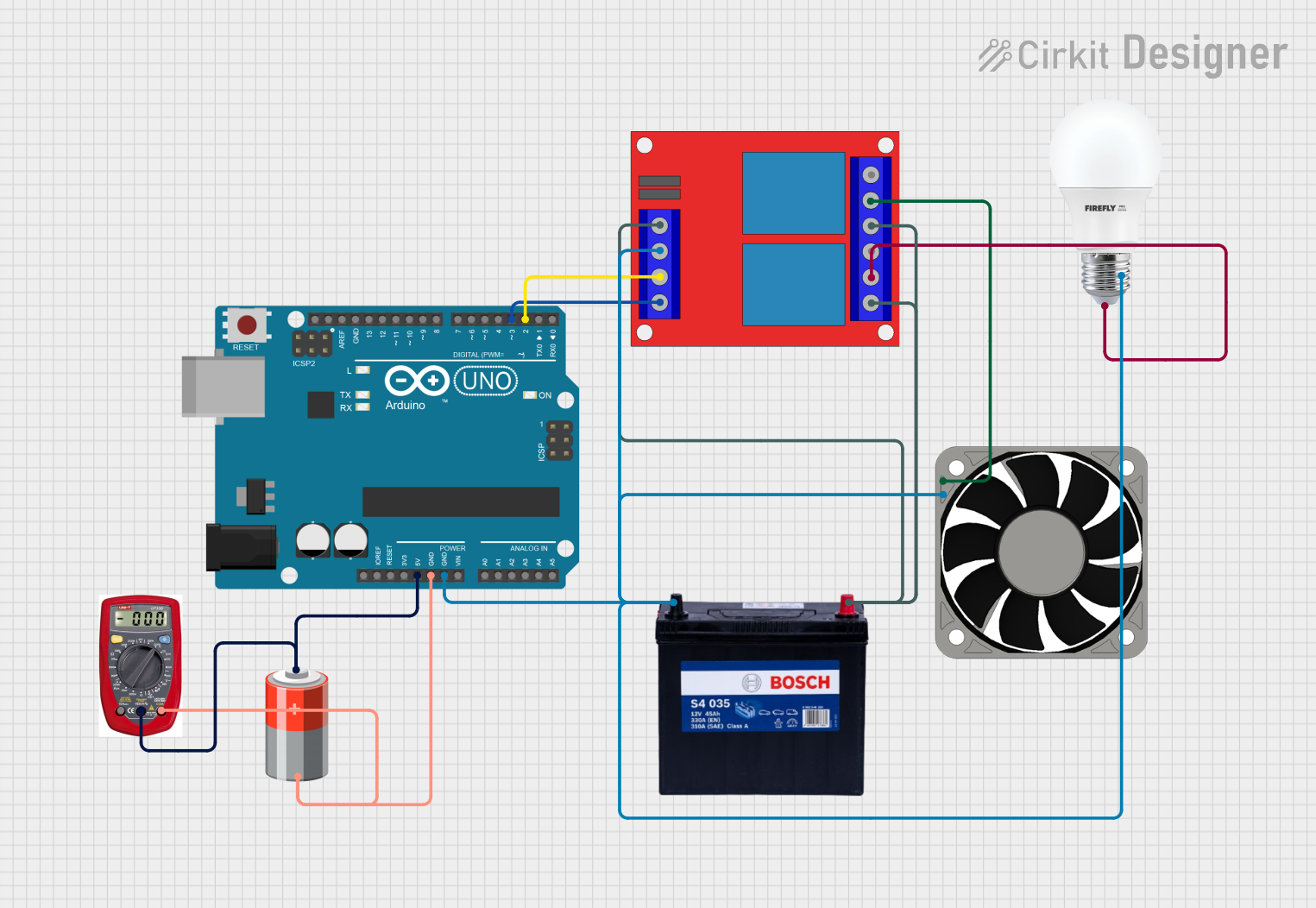
Circuit Documentation
Summary
This circuit is designed to control a 12V fan and a bulb using an Arduino UNO and a 2-channel 12V relay module. The Arduino UNO is powered by a 5V battery, and the fan and bulb are powered by a 12V 200Ah battery. The Arduino UNO controls the relays to switch the fan and bulb on and off in a timed sequence.
Component List
2 Channel 12V Relay
- Description: A relay module that allows control of high voltage devices using low voltage signals.
- Pins: 12v +, 12v -, Trigger 1, Trigger 2, NC1, COM1, NO1, NC2, COM2, NO2
40 Fan 12V
- Description: A 12V fan used for cooling purposes.
- Pins: +12V, -12V
BULB
- Description: A standard bulb used for illumination.
- Pins: +, -
Arduino UNO
- Description: A microcontroller board based on the ATmega328P.
- Pins: UNUSED, IOREF, Reset, 3.3V, 5V, GND, Vin, A0, A1, A2, A3, A4, A5, SCL, SDA, AREF, D13, D12, D11, D10, D9, D8, D7, D6, D5, D4, D3, D2, D1, D0
12V 200Ah Battery
- Description: A high-capacity battery providing 12V power.
- Pins: GND, 12V
5V Battery
- Description: A battery providing 5V power.
- Pins: +, -
Multimeter
- Description: A device used to measure voltage, current, and resistance.
- Pins: COM, V, A
Wiring Details
2 Channel 12V Relay
- 12v + connected to 12V of 12V 200Ah Battery
- 12v - connected to GND of 12V 200Ah Battery
- Trigger 1 connected to D2 of Arduino UNO
- Trigger 2 connected to D3 of Arduino UNO
- NO1 connected to 12V of 12V 200Ah Battery
- COM1 connected to +12V of 40 Fan 12V
- NO2 connected to 12V of 12V 200Ah Battery
- COM2 connected to + of BULB
40 Fan 12V
- +12V connected to COM1 of 2 Channel 12V Relay
- -12V connected to GND of 12V 200Ah Battery
BULB
- + connected to COM2 of 2 Channel 12V Relay
- - connected to GND of 12V 200Ah Battery
Arduino UNO
- GND connected to GND of 12V 200Ah Battery
- GND connected to - of 5V Battery
- 5V connected to + of 5V Battery
- D2 connected to Trigger 1 of 2 Channel 12V Relay
- D3 connected to Trigger 2 of 2 Channel 12V Relay
12V 200Ah Battery
- 12V connected to 12v + of 2 Channel 12V Relay
- GND connected to GND of Arduino UNO
- GND connected to -12V of 40 Fan 12V
- GND connected to - of BULB
- GND connected to 12v - of 2 Channel 12V Relay
5V Battery
- + connected to 5V of Arduino UNO
- - connected to GND of Arduino UNO
Multimeter
- V connected to 5V of Arduino UNO
- COM connected to GND of Arduino UNO
Code Documentation
Arduino UNO Code
void setup() {
  // Initialize the digital pins as outputs
  pinMode(2, OUTPUT); // Relay 1 (Fan)
  pinMode(3, OUTPUT); // Relay 2 (Bulb)
}

void loop() {
  // Turn on Relay 1 (Fan)
  digitalWrite(2, HIGH);
  delay(1000); // Wait for a second
  digitalWrite(2, LOW);
  delay(1000); // Wait for a second

  // Turn on Relay 2 (Bulb)
  digitalWrite(3, HIGH);
  delay(1000); // Wait for a second
  digitalWrite(3, LOW);
  delay(1000); // Wait for a second
}
This code initializes the digital pins 2 and 3 as outputs to control the relays. In the loop, it alternates turning on and off the relays connected to the fan and bulb with a delay of one second.