
Raspberry Pi 4B and OV7725 Camera-Based GSM Security System with Buzzer Alert
View and Edit Project In Cirkit Designer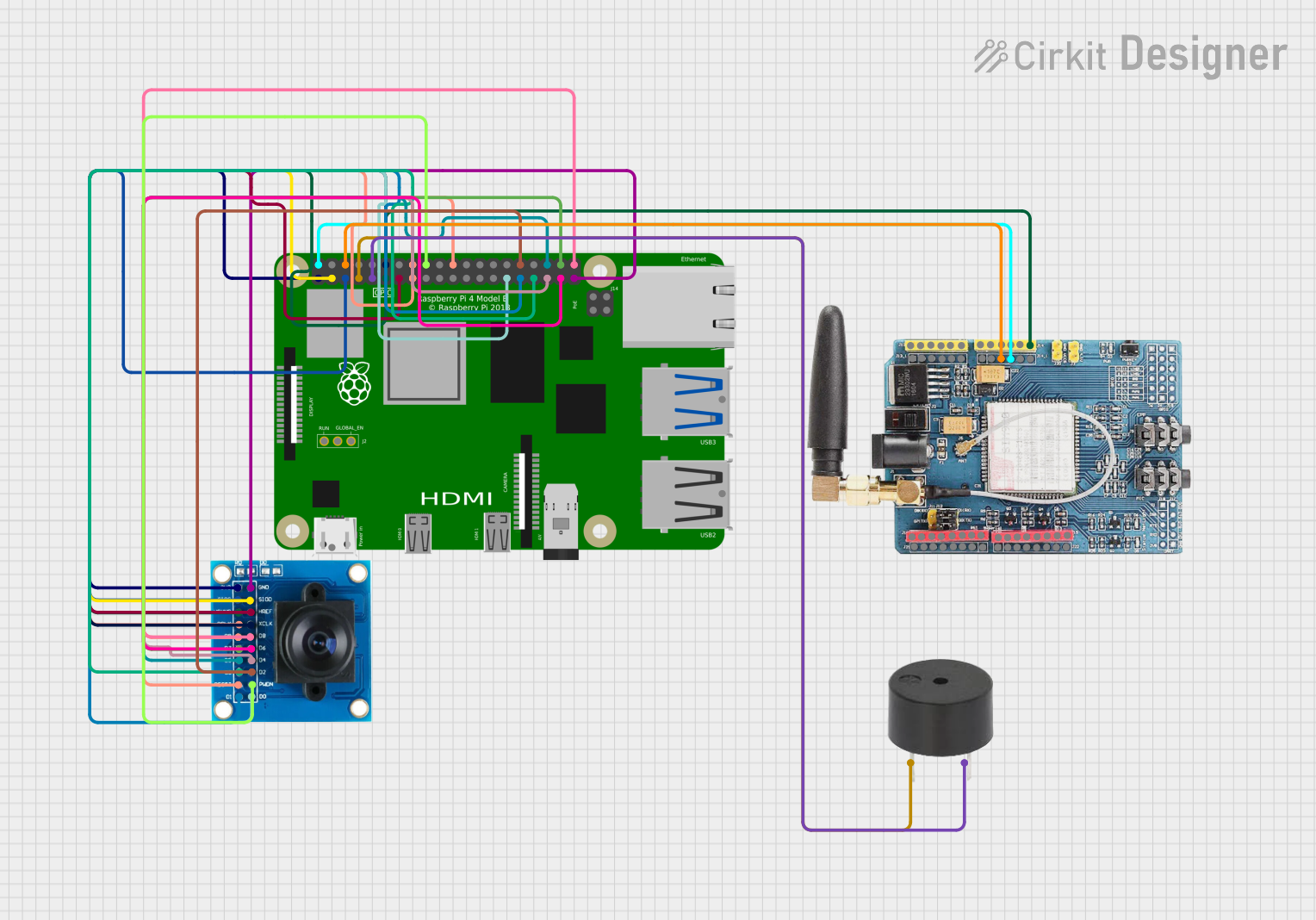
Circuit Documentation
Summary
This document provides a detailed overview of a circuit that integrates a camera module (OV7725), a buzzer, a GSM module (SIM900), and a Raspberry Pi 4B. The Raspberry Pi 4B serves as the central controller, interfacing with the camera, buzzer, and GSM module to perform various functions.
Component List
OV7725 Camera Module
- Description: A camera module used for capturing images.
- Pins: 3V3, GND, SIOC, SIOD, VSYNC, HREF, PCLK, XCLK, D9, D8, D7, D6, D5, D4, D3, D2, RESET, D1, D0, PWDN
Buzzer
- Description: An audio signaling device.
- Pins: PIN, GND
GSM SIM900 Module
- Description: A GSM module used for communication over cellular networks.
- Pins: A5, A4, A3, A2, A1, A0, 5V, GND, 3.3V, RESET, D0, D1, D2, D3, D4, D5, D6, D7, D8, D9, D10, D11, D12, D13, AREF
Raspberry Pi 4B
- Description: A single-board computer used as the central controller.
- Pins: 3V3, 5V, GPIO2, GPIO3, GND, GPIO4, GPIO14, GPIO15, GPIO17, GPIO18, GPIO27, GPIO22, GPIO23, GPIO24, GPIO10, GPIO9, GPIO25, GPIO11, GPIO8, GPIO7, ID_SD, GPIO5, GPIO6, GPIO12, GPIO13, GPIO19, GPIO16, GPIO26, GPIO20, GPIO21, ID_SC, TR01_TAP, TR00_TAP, TR03_TAP, TR02_TAP, RUN, GLOBAL_EN
Wiring Details
OV7725 Camera Module
- 3V3 connected to Raspberry Pi 4B 3V3
- GND connected to Raspberry Pi 4B GND
- SIOD connected to Raspberry Pi 4B GPIO2
- SIOC connected to Raspberry Pi 4B GPIO3
- VSYNC connected to Raspberry Pi 4B GPIO17 and GSM SIM900 RESET
- XCLK connected to Raspberry Pi 4B GPIO18
- HREF connected to Raspberry Pi 4B GPIO27
- RESET connected to OV7725 PCLK, OV7725 D9, Raspberry Pi 4B GPIO22, Raspberry Pi 4B GPIO23, and Raspberry Pi 4B GPIO25
- PWDN connected to Raspberry Pi 4B GPIO24
- D0 connected to Raspberry Pi 4B GPIO5
- D1 connected to Raspberry Pi 4B GPIO6
- D2 connected to Raspberry Pi 4B GPIO12
- D3 connected to Raspberry Pi 4B GPIO13
- D4 connected to Raspberry Pi 4B GPIO19
- D5 connected to Raspberry Pi 4B GPIO16
- D6 connected to Raspberry Pi 4B GPIO26
- D7 connected to Raspberry Pi 4B GPIO20
- D8 connected to Raspberry Pi 4B GPIO21
Buzzer
- PIN connected to Raspberry Pi 4B GPIO4
- GND connected to Raspberry Pi 4B GND
GSM SIM900 Module
- 5V connected to Raspberry Pi 4B 5V
- GND connected to Raspberry Pi 4B GND
- RESET connected to OV7725 VSYNC and Raspberry Pi 4B GPIO17
Raspberry Pi 4B
- 3V3 connected to OV7725 3V3
- 5V connected to GSM SIM900 5V
- GPIO2 connected to OV7725 SIOD
- GPIO3 connected to OV7725 SIOC
- GND connected to OV7725 GND, GSM SIM900 GND, and Buzzer GND
- GPIO4 connected to Buzzer PIN
- GPIO17 connected to OV7725 VSYNC and GSM SIM900 RESET
- GPIO18 connected to OV7725 XCLK
- GPIO27 connected to OV7725 HREF
- GPIO22 connected to OV7725 RESET
- GPIO23 connected to OV7725 RESET
- GPIO25 connected to OV7725 RESET
- GPIO24 connected to OV7725 PWDN
- GPIO5 connected to OV7725 D0
- GPIO6 connected to OV7725 D1
- GPIO12 connected to OV7725 D2
- GPIO13 connected to OV7725 D3
- GPIO19 connected to OV7725 D4
- GPIO16 connected to OV7725 D5
- GPIO26 connected to OV7725 D6
- GPIO20 connected to OV7725 D7
- GPIO21 connected to OV7725 D8
Code
No code is provided for this circuit.
This document provides a comprehensive overview of the circuit, including the components used, their connections, and the absence of any embedded code.