
Circuit Documentation
Summary of the Circuit
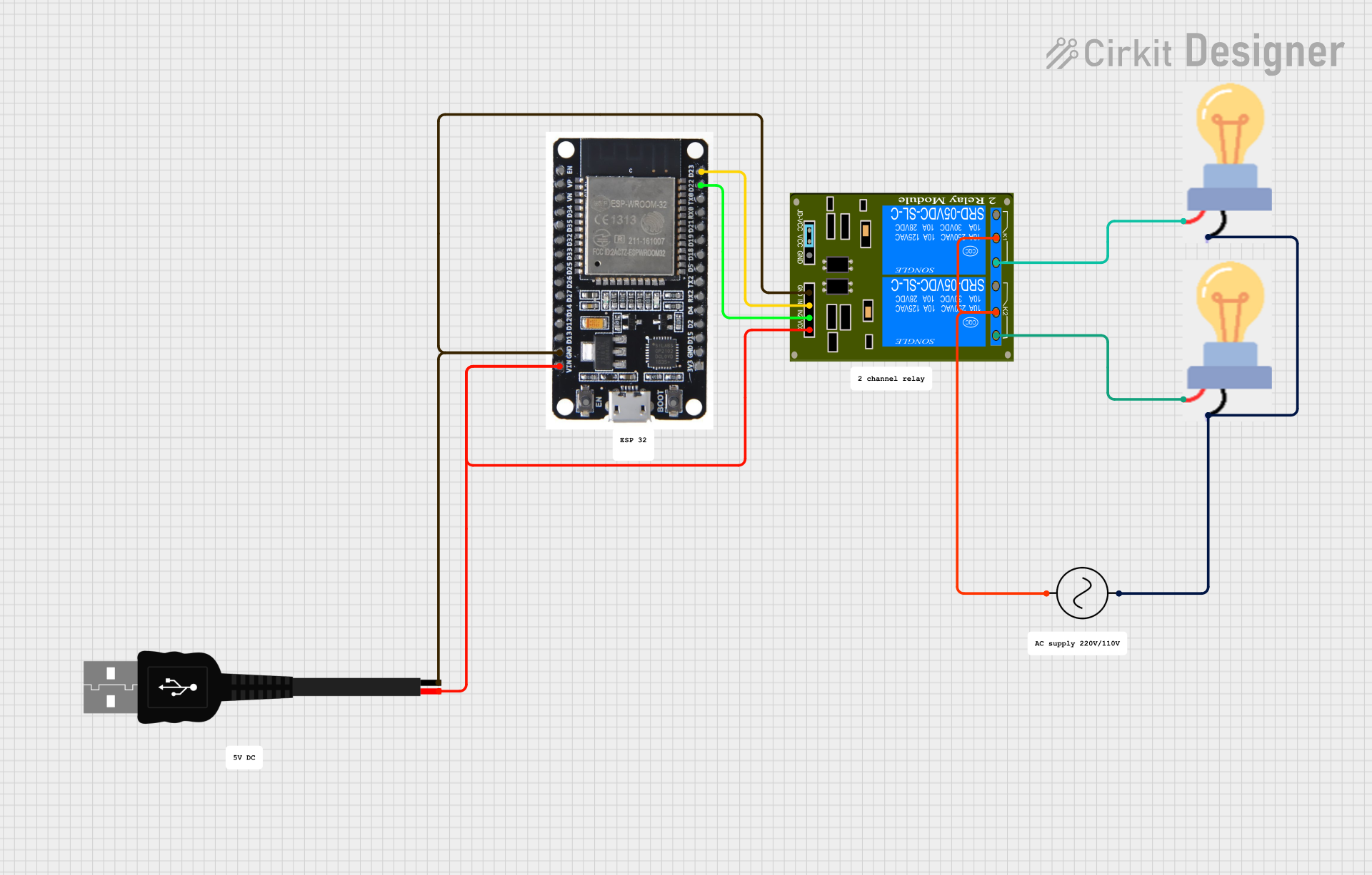
The circuit described by the provided inputs consists of an ESP32 microcontroller, a 2-Channel Relay module, two bulbs, an AC power supply, and a USB male 2-pin connection. The ESP32 is powered via the USB connection and controls the relay module, which in turn switches the two bulbs on and off. The AC supply provides power to the bulbs through the relay contacts. The ESP32's GPIO pins are used to control the relay inputs, and the ground and power lines are distributed among the components to complete the circuit.
Component List
Ac Supply
- Description: Provides alternating current (AC) power to the circuit.
- Pins: +ve (positive), -ve (negative)
ESP32
- Description: A microcontroller with Wi-Fi and Bluetooth capabilities.
- Pins: EN, VP, VN, D34, D35, D32, D33, D25, D26, D27, D14, D12, D13, GND, VIN, 3V3, D15, D2, D4, RX2, TX2, D5, D18, D19, D21, RX0, TX0, D22, D23, BOOT
Bulb
- Description: An electric light source.
- Pins: GND (ground), power
2-Channel Relay (5V 10A)
- Description: A relay module with two channels that can switch AC or DC loads.
- Pins: K1-Off, K1-In, K2-On, K2-In, K1-On, K2-Off, VCC, JD-GND, IN2, IN1, GND
USB male 2 pin connection
- Description: A USB connector used for power supply to the circuit.
- Pins: Negative (-), Positive (+)
Wiring Details
Ac Supply
- -ve: Connected to the common input terminals of the relay module (K1-In, K2-In).
- +ve: Connected to the ground pins of both bulbs.
ESP32
- GND: Connected to the ground (GND) pin of the USB connection and the ground (GND) pin of the relay module.
- VIN: Connected to the positive (+) pin of the USB connection.
- D22: Connected to the IN2 pin of the relay module.
- D23: Connected to the IN1 pin of the relay module.
Bulb 1
- GND: Connected to the +ve pin of the AC supply.
- power: Connected to the K2-On pin of the relay module.
Bulb 2
- GND: Connected to the +ve pin of the AC supply.
- power: Connected to the K1-On pin of the relay module.
2-Channel Relay (5V 10A)
- GND: Connected to the GND pin of the ESP32 and the Negative (-) pin of the USB connection.
- VCC: Connected to the Positive (+) pin of the USB connection.
- IN2: Connected to the D22 pin of the ESP32.
- IN1: Connected to the D23 pin of the ESP32.
- K1-In, K2-In: Connected to the -ve pin of the AC supply.
- K2-On: Connected to the power pin of Bulb 1.
- K1-On: Connected to the power pin of Bulb 2.
USB male 2 pin connection
- Negative (-): Connected to the GND pins of the ESP32 and the relay module.
- Positive (+): Connected to the VIN pin of the ESP32 and the VCC pin of the relay module.
Documented Code
No code was provided for the microcontroller in the circuit. Therefore, this section is not applicable for the current documentation. If code is added later, it should be documented here with explanations of how the microcontroller interfaces with the relay module and any other logic or functionality implemented.