Arduino Mega 2560 Controlled Security System with Fingerprint Access and Door Lock
Circuit Documentation
Summary
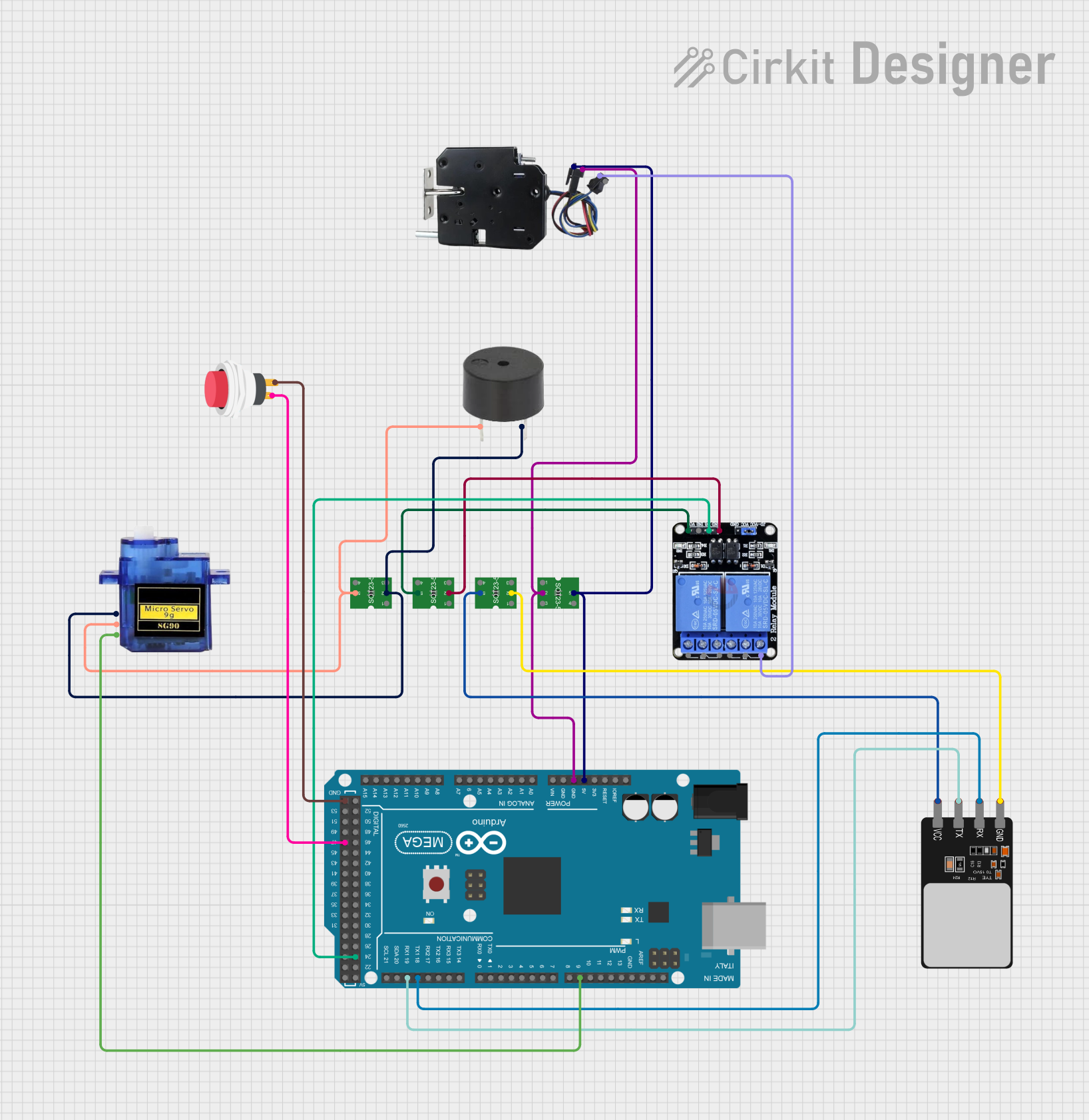
This document provides a detailed overview of a circuit designed to interface an Arduino Mega 2560 with various peripherals including a micro servo, a voltage regulator, a buzzer, a two-channel relay, a fingerprint scanner, a push switch, and a door lock. The circuit is powered through voltage regulators that ensure stable voltage supply to the components. Communication between the Arduino and the fingerprint scanner is established via serial communication. The micro servo and the buzzer are controlled by PWM signals, and the door lock is operated through a relay which is in turn controlled by the Arduino. A push switch is used to provide input to the Arduino.
Component List
Arduino Mega 2560
- Microcontroller board based on the ATmega2560
- Provides a large number of IO pins including digital, analog, PWM, and communication pins
Micro Servo 9G
- Small and lightweight servo motor
- Operates on +5V and controlled via a PWM signal
Voltage Regulator
- Provides a stable output voltage from a variable input voltage
- Commonly used to supply a consistent voltage to electronic components
Buzzer
- An electromechanical component that emits sound when energized
- Typically used for audible alerts or notifications
Two Channel Relay 5V
- An electrically operated switch that allows control of a high power circuit by a low power signal
- Has two channels that can be controlled independently
Fingerprint Scanner
- Biometric sensor that captures fingerprints for identification purposes
- Interfaces with the Arduino via serial communication
2Pin Push Switch
- A simple switch that closes the circuit when pressed
- Used to provide a binary input to the Arduino
Door Lock
- An electronic lock that can be controlled remotely
- Operated by the relay, allowing the Arduino to lock or unlock the door
Wiring Details
Arduino Mega 2560
5Vconnected to theOUTpin of a Voltage Regulator andVCCof the Door LockGNDconnected to theGNDpins of the Door Lock, Micro Servo 9G, Buzzer, and Voltage RegulatorD19/RX1connected toTXof the Fingerprint ScannerD18/TX1connected toRXof the Fingerprint ScannerD9 PWMconnected toPWMof the Micro Servo 9GD24connected toIN1of the Two Channel Relay 5VD47connected toInput +of the 2Pin Push Switch
Micro Servo 9G
PWMconnected toD9 PWMon the Arduino Mega 2560GNDconnected to the common ground net+5Vconnected to theOUTpin of a Voltage Regulator
Voltage Regulator
- Multiple instances are used, each providing power to different components
OUTpin provides regulated voltage to the Arduino Mega 2560, Micro Servo 9G, Buzzer, Two Channel Relay 5V, and Fingerprint ScannerGNDpin connected to the common ground net
Buzzer
PINconnected to theOUTpin of a Voltage RegulatorGNDconnected to the common ground net
Two Channel Relay 5V
IN1connected toD24on the Arduino Mega 2560VCCconnected to theOUTpin of a Voltage RegulatorGNDconnected to the common ground netNO1connected toINof the Door Lock
Fingerprint Scanner
VCCconnected to theOUTpin of a Voltage RegulatorTXconnected toD19/RX1on the Arduino Mega 2560RXconnected toD18/TX1on the Arduino Mega 2560GNDconnected to the common ground net
2Pin Push Switch
Input +connected toD47on the Arduino Mega 2560Output +connected toGNDon the Arduino Mega 2560
Door Lock
VCCconnected to5Von the Arduino Mega 2560GNDconnected to the common ground netINconnected toNO1on the Two Channel Relay 5V
Documented Code
Arduino Mega 2560 - sketch.ino
void setup() {
  // put your setup code here, to run once:

}

void loop() {
  // put your main code here, to run repeatedly:

}
Arduino Mega 2560 - documentation.txt
(No additional documentation provided for the code)
This concludes the documentation for the circuit. The wiring details provide the necessary information to replicate the circuit connections, and the code section provides the basic structure for the Arduino sketch. Additional functionality can be added to the sketch based on the specific requirements of the project.