Arduino Heartbeat Sensor with OLED Display
Circuit Documentation
Summary
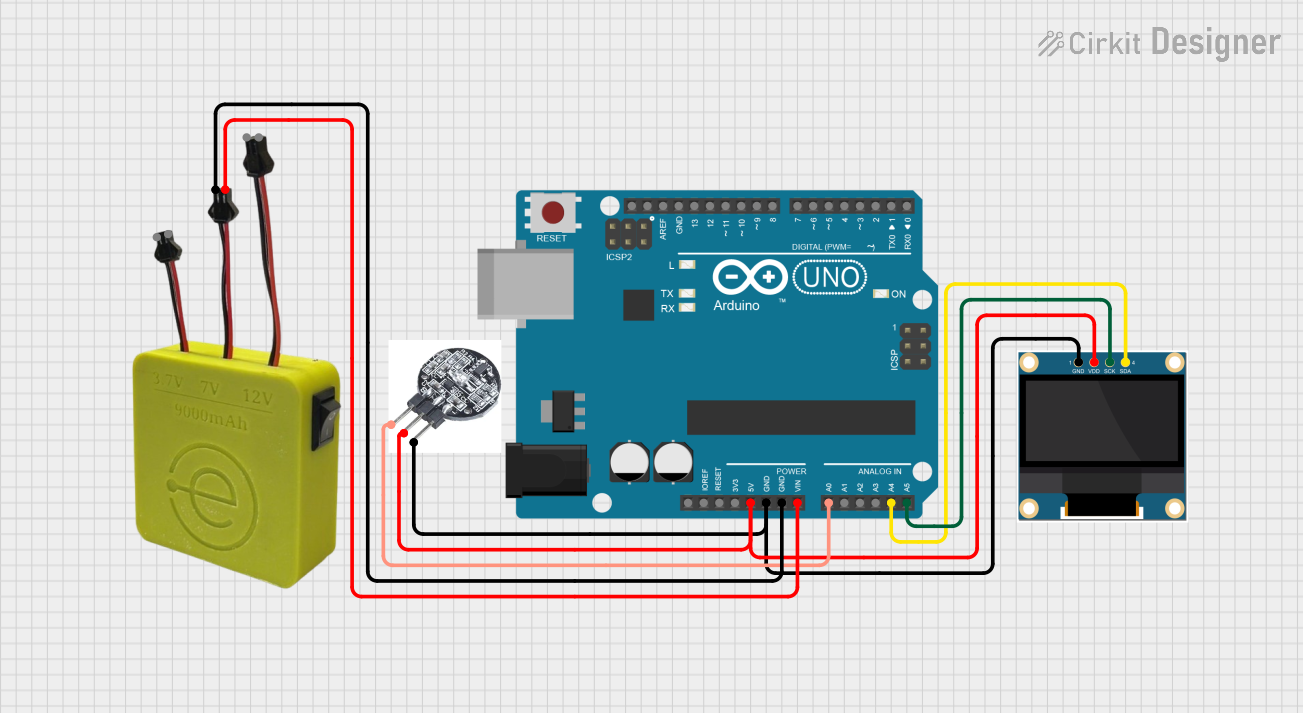
This circuit is designed to interface an Arduino UNO with a heartbeat sensor and a 0.96" OLED display. The heartbeat sensor captures heart rate data, which is then processed by the Arduino and displayed on the OLED screen. The MAHIR 12.0 power supply is used to provide the necessary voltage levels for the components.
Component List
Arduino UNO
- Description: A microcontroller board based on the ATmega328P. It is used for programming and controlling the circuit.
- Purpose: Acts as the main controller for processing data from the heartbeat sensor and sending it to the OLED display.
Heartbeat Sensor
- Description: A sensor that detects heartbeats and outputs a signal corresponding to the heart rate.
- Purpose: Captures heart rate data to be processed by the Arduino.
0.96" OLED
- Description: A small OLED display used for visual output.
- Purpose: Displays the heart rate data processed by the Arduino.
MAHIR 12.0
- Description: A power supply module that provides multiple voltage outputs.
- Purpose: Supplies power to the Arduino and other components in the circuit.
Wiring Details
Arduino UNO
5V: Connected to the VDD pin of the 0.96" OLED and the VCC pin of the heartbeat sensor.
GND: Connected to the GND pins of the 0.96" OLED and the heartbeat sensor, as well as the GND pin of the MAHIR 12.0.
Vin: Connected to the 7V pin of the MAHIR 12.0.
A0: Connected to the S pin of the heartbeat sensor.
A4: Connected to the SDA pin of the 0.96" OLED.
A5: Connected to the SCK pin of the 0.96" OLED.
Heartbeat Sensor
VCC: Connected to the 5V pin of the Arduino UNO.
GND: Connected to the GND pin of the Arduino UNO.
S: Connected to the A0 pin of the Arduino UNO.
0.96" OLED
VDD: Connected to the 5V pin of the Arduino UNO.
GND: Connected to the GND pin of the Arduino UNO.
SDA: Connected to the A4 pin of the Arduino UNO.
SCK: Connected to the A5 pin of the Arduino UNO.
MAHIR 12.0
GND: Connected to the GND pin of the Arduino UNO.
7V: Connected to the Vin pin of the Arduino UNO.
Documented Code
Arduino Code
void setup() {
  // put your setup code here, to run once:

}

void loop() {
  // put your main code here, to run repeatedly:

}
Documentation
This section is reserved for additional documentation or notes related to the circuit and its components.
This documentation provides a comprehensive overview of the circuit, detailing the components used, their wiring connections, and the code implemented in the Arduino UNO.