Cirkit Designer
Your all-in-one circuit design IDE
Home /
Project Documentation
Solar-Powered Arduino Mega 2560 Control System
Solar-Powered Arduino Circuit Documentation
Summary
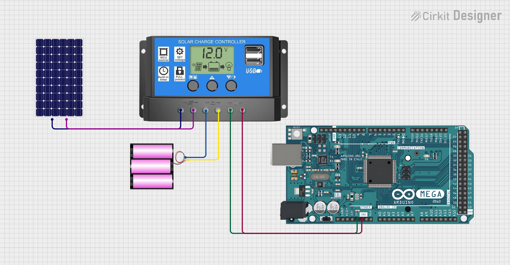
This document outlines the design and functionality of a solar-powered circuit that is designed to harness solar energy to power an Arduino Mega 2560 microcontroller. The circuit includes a solar panel, a 12V battery, a solar charge controller, and the Arduino Mega 2560. The solar panel charges the battery through the solar charge controller, which also provides a regulated power supply to the Arduino. The Arduino is programmed to perform tasks as per the user's requirements.
Component List
Solar Panel
- Description: A photovoltaic panel designed to convert sunlight into electrical energy.
- Pins:
+(Positive),-(Negative)
Battery 12V
- Description: A 12-volt rechargeable battery that stores electrical energy.
- Pins:
+(Positive),-(Negative)
Solar Charge Controller
- Description: A device that regulates the voltage and current coming from the solar panels going to the battery.
- Pins:
Solar Cell +,Solar Cell -,Battery +,Battery -,Load +,Load -
Arduino Mega 2560
- Description: A microcontroller board based on the ATmega2560, with a wide range of input/output options.
- Pins: Multiple digital and analog pins, power supply pins (
IOREF,RESET,3V3,5V,GND,VIN), and communication pins (A0-A15,D21/SCL,D20/SDA,D19/RX1,D18/TX1, etc.)
Wiring Details
Solar Panel
+connected toSolar Charge ControllerSolar Cell +-connected toSolar Charge ControllerSolar Cell -
Battery 12V
+connected toSolar Charge ControllerBattery +-connected toSolar Charge ControllerBattery -
Solar Charge Controller
Solar Cell +connected toSolar Panel+Solar Cell -connected toSolar Panel-Battery +connected toBattery 12V+Battery -connected toBattery 12V-Load +connected toArduino Mega 25605VLoad -connected toArduino Mega 2560GND
Arduino Mega 2560
5Vconnected toSolar Charge ControllerLoad +GNDconnected toSolar Charge ControllerLoad -
Documented Code
Arduino Mega 2560 Code - sketch.ino
void setup() {
  // put your setup code here, to run once:

}

void loop() {
  // put your main code here, to run repeatedly:

}
Additional Notes
- The
documentation.txtfile for the Arduino Mega 2560 is currently empty and does not contain any additional information or code.
This concludes the documentation for the solar-powered Arduino circuit. The circuit is designed to be energy-efficient and environmentally friendly, utilizing renewable solar energy to power the microcontroller for various applications.