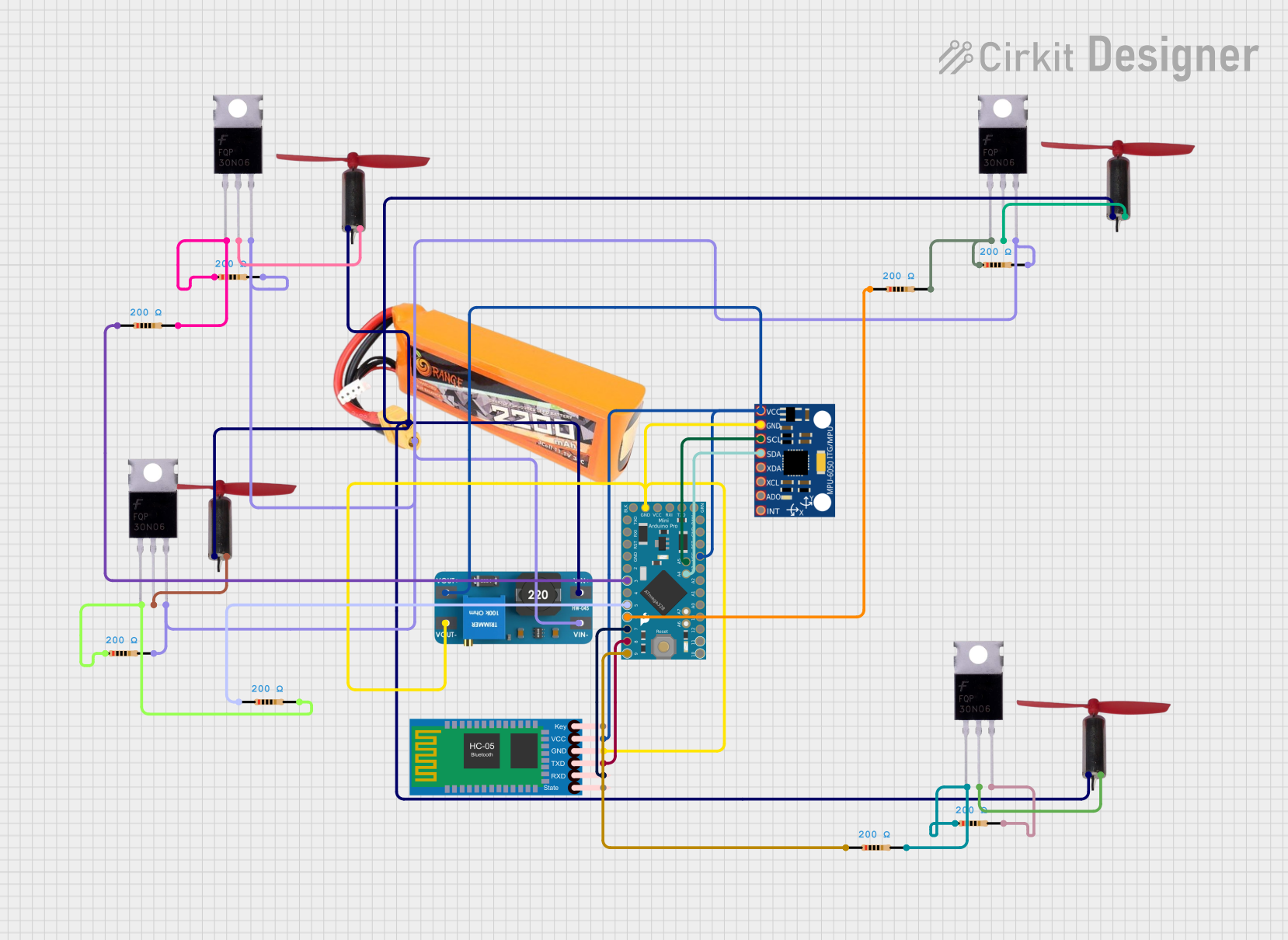
Arduino Pro Mini and HC-05 Bluetooth Controlled Coreless Motor Clock with MPU-6050 Feedback

Circuit Documentation
Summary
This circuit integrates a microcontroller, sensors, communication modules, power management, and motor control components to create a system capable of interfacing with a Bluetooth module and MPU-6050 sensor, driving multiple coreless motors, and managing power through a boost converter. The Arduino Pro Mini serves as the central processing unit, interfacing with the HC-05 Bluetooth Module for wireless communication and the MPU-6050 for motion tracking. The boost converter MT3608 steps up the voltage from a LiPo battery to power the system, and MOSFETs, in conjunction with resistors, control the coreless motors.
Component List
- Arduino Pro Mini: A compact microcontroller board based on the ATmega328, ideal for embedding into projects.
- HC-05 Bluetooth Module: A Bluetooth module for wireless communication.
- Boost Converter MT3608: A module that steps up the input voltage to a higher output voltage.
- Coreless Motor Clock: Small, lightweight motors used for precise movements.
- Mosfet: A type of transistor used for switching electronic signals.
- Resistor: A passive two-terminal electrical component that implements electrical resistance as a circuit element.
- MPU-6050: A motion tracking device that combines a 3-axis gyroscope and a 3-axis accelerometer.
- LiPo Battery 2200mAh 30C: A rechargeable battery that provides power to the circuit.
Wiring Details
Arduino Pro Mini
- GND: Connected to the ground planes of MPU-6050, HC-05 Bluetooth Module, and boost converter MT3608.
- VCC: Powers the MPU-6050, HC-05 Bluetooth Module, and is connected to the output of the boost converter MT3608.
- A4 (SDA): Connected to the SDA pin of the MPU-6050 for I2C communication.
- A5 (SCL): Connected to the SCL pin of the MPU-6050 for I2C communication.
- D9: Connected to a resistor leading to a MOSFET gate.
- D8: Connected to the TXD pin of the HC-05 Bluetooth Module.
- D7: Connected to the RXD pin of the HC-05 Bluetooth Module.
- D6: Connected to a resistor leading to a MOSFET gate.
- D5: Connected to a resistor leading to a MOSFET gate.
- D3: Connected to a resistor leading to a MOSFET gate.
HC-05 Bluetooth Module
- GND: Connected to the ground plane.
- VCC: Powered by the output of the boost converter MT3608.
- TXD: Connected to D8 on the Arduino Pro Mini.
- RXD: Connected to D7 on the Arduino Pro Mini.
Boost Converter MT3608
- OUTPUT +: Connected to the VCC of Arduino Pro Mini, MPU-6050, and HC-05 Bluetooth Module.
- OUTPUT -: Connected to the ground plane.
- INPUT +: Connected to the positive terminal of the LiPo battery and the positive terminals of all coreless motors.
- INPUT -: Connected to the ground plane and the negative terminal of the LiPo battery.
Coreless Motor Clock
- +: Connected to the INPUT + of the boost converter MT3608.
- -: Connected to the Drain of a corresponding MOSFET.
Mosfet
- Gate: Connected to a resistor which is then connected to a digital pin on the Arduino Pro Mini.
- Drain: Connected to the negative terminal of a corresponding Coreless Motor Clock.
- Source: Connected to the ground plane.
Resistor
- pin1: Connected to a digital pin on the Arduino Pro Mini or to the Gate of a MOSFET.
- pin2: Connected to the ground plane or to the Source of a MOSFET.
MPU-6050
- GND: Connected to the ground plane.
- VCC: Powered by the output of the boost converter MT3608.
- SCL: Connected to A5 on the Arduino Pro Mini.
- SDA: Connected to A4 on the Arduino Pro Mini.
LiPo Battery 2200mAh 30C
- VCC: Connected to the INPUT + of the boost converter MT3608.
- GND: Connected to the ground plane.
Documented Code
Arduino Pro Mini Code (sketch.ino)
void setup() {
  // put your setup code here, to run once:

}

void loop() {
  // put your main code here, to run repeatedly:

}
Note: The provided code is a template and does not include specific functionality. It should be populated with the setup and loop routines required for the intended operation of the circuit.