Cirkit Designer
Your all-in-one circuit design IDE
Home /
Project Documentation
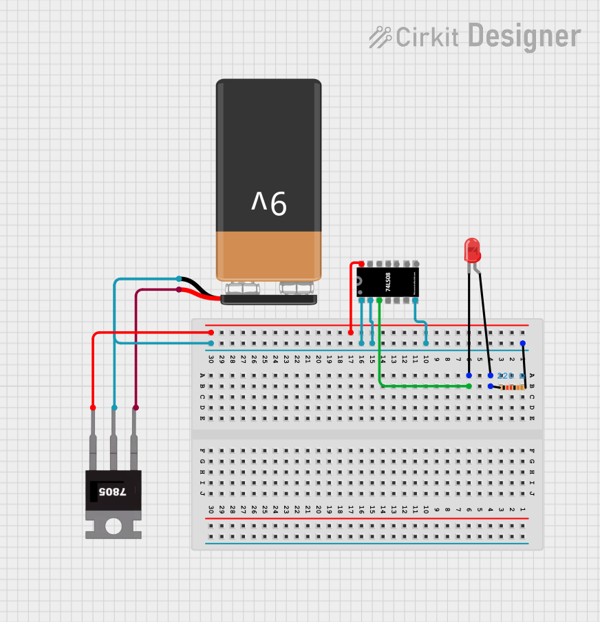
Battery-Powered LED Indicator with 7408 AND Gate
Circuit Documentation
Summary
This circuit consists of a 9V battery, a 7805 voltage regulator, an IC 7408 (quad 2-input AND gate), a red LED, and a resistor. The 9V battery powers the circuit, and the 7805 voltage regulator steps down the voltage to 5V for the IC 7408. The IC 7408 processes input signals and drives the LED through a current-limiting resistor.
Component List
9V Battery
- Description: Provides the primary power source for the circuit.
- Pins:
+,-
7805 Voltage Regulator
- Description: Steps down the 9V from the battery to a stable 5V for the IC 7408.
- Pins:
Vin,Gnd,Vout
IC 7408 (Quad 2-Input AND Gate)
- Description: Contains four independent AND gates.
- Pins:
A1,B1,Y1,A2,B2,Y2,GND,Vcc,B4,A4,Y4,A3,B3,Y3
LED: Two Pin (Red)
- Description: Emits light when current flows through it.
- Pins:
cathode,anode
Resistor
- Description: Limits the current flowing through the LED.
- Pins:
pin1,pin2 - Properties:
- Resistance: 220 Ohms
Wiring Details
9V Battery
- + is connected to
Vinof the 7805 voltage regulator. - - is connected to
Gndof the 7805 voltage regulator andGNDof the IC 7408.
7805 Voltage Regulator
- Vin is connected to
+of the 9V battery. - Gnd is connected to
-of the 9V battery andGNDof the IC 7408. - Vout is connected to
Vccof the IC 7408.
IC 7408 (Quad 2-Input AND Gate)
- GND is connected to
Gndof the 7805 voltage regulator and-of the 9V battery. - Vcc is connected to
Voutof the 7805 voltage regulator. - Y1 is connected to
cathodeof the LED. - A1 is connected to
pin2of the resistor. - B1 is connected to
pin2of the resistor.
LED: Two Pin (Red)
- cathode is connected to
Y1of the IC 7408. - anode is connected to
pin1of the resistor.
Resistor
- pin1 is connected to
anodeof the LED. - pin2 is connected to
A1andB1of the IC 7408.
Code
There is no microcontroller code associated with this circuit.
This documentation provides a comprehensive overview of the circuit, including a summary, detailed component descriptions, wiring details, and any associated code.