
Circuit Documentation
Summary
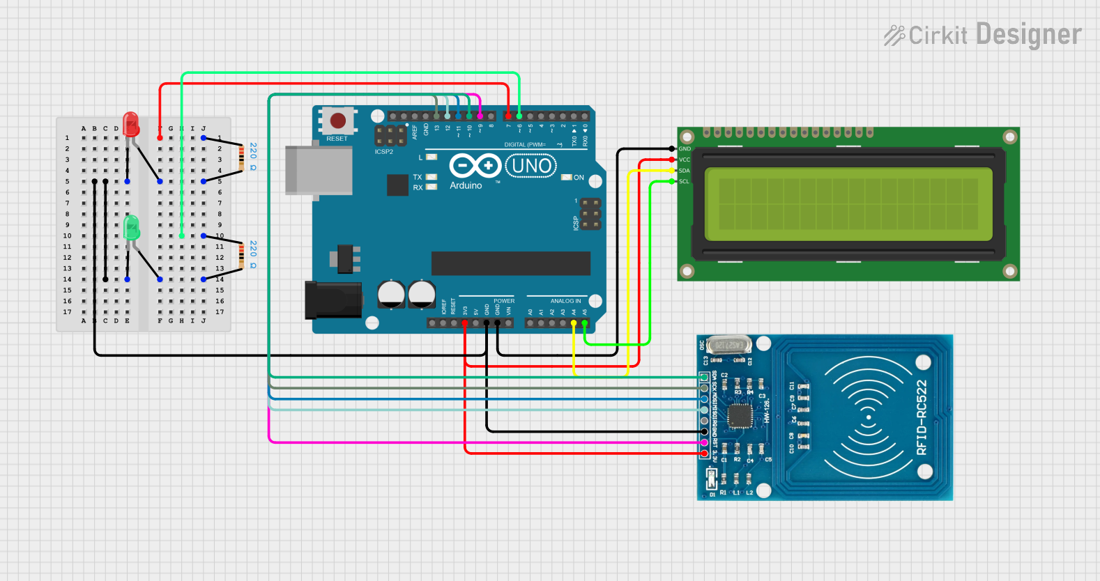
This circuit is designed around an Arduino UNO microcontroller and includes various peripherals such as an RFID-RC522 module for RFID reading, a 16x2 I2C LCD for display purposes, and two LEDs (red and green) for status indication. The circuit is powered by the Arduino's 3.3V output, which is also used to power the RFID module and the LCD. The LEDs are connected to digital pins on the Arduino through 220-ohm resistors to limit the current. The RFID module communicates with the Arduino via the SPI interface, while the LCD uses the I2C protocol.
Component List
Arduino UNO
- Microcontroller board based on the ATmega328P
- Provides digital I/O pins, analog inputs, a USB connection for programming, and power supply pins
LED: Two Pin (red)
- A red LED used for status indication
LED: Two Pin (green)
- A green LED used for status indication
16x2 I2C LCD
- A 16-character by 2-line display that communicates over the I2C bus
Resistor (220 Ohms)
- Two resistors used to limit the current through the LEDs
RFID-RC522
- An RFID reader/writer module that operates at 13.56 MHz
Wiring Details
Arduino UNO
3.3Vconnected to RFID-RC522 VCC and 16x2 I2C LCD VCCGNDconnected to RFID-RC522 GND, 16x2 I2C LCD GND, and common cathode of both LEDsA4 (SDA)connected to 16x2 I2C LCD SDAA5 (SCL)connected to 16x2 I2C LCD SCLD13 (SCK)connected to RFID-RC522 SCKD12 (MISO)connected to RFID-RC522 MISOD11 (MOSI)connected to RFID-RC522 MOSID10 (SS)connected to RFID-RC522 SDAD9connected to RFID-RC522 RSTD7connected to one end of a 220-ohm resistor (other end connected to red LED anode)D6connected to one end of a 220-ohm resistor (other end connected to green LED anode)
LED: Two Pin (red)
cathodeconnected to common groundanodeconnected to a 220-ohm resistor, which is connected to Arduino UNO D7
LED: Two Pin (green)
cathodeconnected to common groundanodeconnected to a 220-ohm resistor, which is connected to Arduino UNO D6
16x2 I2C LCD
GNDconnected to Arduino UNO GNDVCCconnected to Arduino UNO 3.3VSDAconnected to Arduino UNO A4SCLconnected to Arduino UNO A5
Resistor (220 Ohms)
- One resistor connected between Arduino UNO D7 and red LED anode
- One resistor connected between Arduino UNO D6 and green LED anode
RFID-RC522
VCC (3.3V)connected to Arduino UNO 3.3VRSTconnected to Arduino UNO D9GNDconnected to common groundIRQnot connectedMISOconnected to Arduino UNO D12MOSIconnected to Arduino UNO D11SCKconnected to Arduino UNO D13SDAconnected to Arduino UNO D10
Documented Code
#include <SPI.h>
#include <MFRC522.h>
#include <Wire.h>
#include <LiquidCrystal_I2C.h>

#define SS_PIN 10
#define RST_PIN 9

#define LED_DENIED_PIN 7
#define LED_ACCESS_PIN 6

LiquidCrystal_I2C lcd(0x3F,16,2);
MFRC522 mfrc522(SS_PIN, RST_PIN); // Instance of the class

int code[] = {32,154,149,117}; //This is the stored UID (Unlock Card)
int codeRead = 0;
String uidString;

void setup() {
   Serial.begin(9600);
   SPI.begin();       // Init SPI bus
   mfrc522.PCD_Init(); // Init MFRC522
   Serial.println("Arduino RFID reading UID");

   pinMode(LED_DENIED_PIN, OUTPUT);
   pinMode(LED_ACCESS_PIN, OUTPUT);

   lcd.init();
   lcd.backlight();
   lcd.setCursor(0,0);
   lcd.print("Show your card:)");
}

void loop() {
   if (mfrc522.PICC_IsNewCardPresent()) {
       if (mfrc522.PICC_ReadCardSerial()) {
           lcd.clear();
           Serial.print("Tag UID:");
           lcd.setCursor(0,0);
           lcd.print("Tag UID:");
           lcd.setCursor(0,1);
           for (byte i = 0; i < mfrc522.uid.size; i++) {
                  Serial.print(mfrc522.uid.uidByte[i] < 0x10 ? " 0" : " ");
                  Serial.print(mfrc522.uid.uidByte[i], HEX);

                  lcd.print(mfrc522.uid.uidByte[i] < 0x10 ? " 0" : " ");
                  lcd.print(mfrc522.uid.uidByte[i], HEX);
            }

            Serial.println();

            int i = 0;
            boolean match = true;
            while(i<mfrc522.uid.size) {
               if(!(int(mfrc522.uid.uidByte[i]) == int(code[i]))) {
                  match = false;
               }
              i++;
            }

            delay(3000);
           lcd.clear();
           lcd.setCursor(0,0);

           if(match) {
              digitalWrite(LED_ACCESS_PIN, HIGH);
              lcd.print("Authorized access");
           } else {
              digitalWrite(LED_DENIED_PIN, HIGH);
              lcd.print(" Access denied  ");
              Serial.println("\nUnknown Card");
           }

             Serial.println("============================");

             mfrc522.PICC_HaltA();

             delay(3000);
             reset_state();
        }
   }
}

void reset_state() {
    lcd.clear();
    lcd.setCursor(0,0);
    lcd.print("Show your card:)");

    digitalWrite(LED_ACCESS_PIN, LOW);
    digitalWrite(LED_DENIED_PIN, LOW);
}
This code is responsible for initializing the RFID reader and the LCD display, reading RFID tags, comparing the read UID with a stored UID, and then turning on the appropriate LED based on whether the UID matches. The LCD displays messages to guide the user and to show the UID of the scanned tag.