
Arduino UNO Based Vibration Detection System with Alert Indicators
View and Edit Project In Cirkit Designer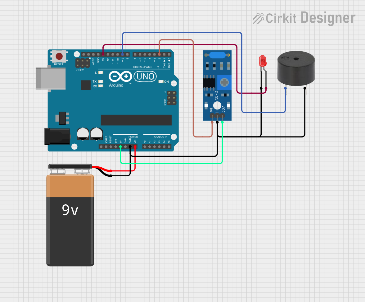
Circuit Documentation
Summary
This circuit is designed around an Arduino UNO microcontroller and includes a 9V battery for power, a SW-420 vibration sensor for detecting vibrations, a red two-pin LED as an indicator, and a buzzer for audible alerts. The Arduino UNO reads the state of the vibration sensor and activates the LED and buzzer when vibrations are detected. The circuit is powered by the 9V battery connected to the Arduino's Vin pin, and the ground connections are shared among all components.
Component List
Arduino UNO
- Description: A microcontroller board based on the ATmega328P.
- Purpose: Acts as the central processing unit of the circuit, reading sensor inputs and controlling outputs such as the LED and buzzer.
9V Battery
- Description: A standard 9-volt battery.
- Purpose: Provides power to the Arduino UNO and the entire circuit.
SW-420 Vibration Sensor
- Description: A module that detects vibrations and outputs a digital signal.
- Purpose: Senses vibrations and sends a signal to the Arduino UNO.
LED: Two Pin (red)
- Description: A basic red LED with an anode and cathode.
- Purpose: Serves as a visual indicator that is turned on when vibrations are detected.
Buzzer
- Description: An electronic buzzer capable of emitting sound.
- Purpose: Emits an audible alert when vibrations are detected.
Wiring Details
Arduino UNO
- 5V: Powers the SW-420 Vibration Sensor.
- GND: Common ground for the 9V Battery, LED, buzzer, and SW-420 Vibration Sensor.
- Vin: Connected to the positive terminal of the 9V Battery.
- D13: Connected to the anode of the LED.
- D9: Connected to the PIN of the buzzer.
- D2: Connected to the Digital output of the SW-420 Vibration Sensor.
9V Battery
- +: Connected to the Vin of the Arduino UNO.
- -: Connected to the GND of the Arduino UNO.
SW-420 Vibration Sensor
- vcc: Connected to the 5V of the Arduino UNO.
- Ground: Connected to the GND of the Arduino UNO.
- Digital output: Connected to the D2 of the Arduino UNO.
LED: Two Pin (red)
- anode: Connected to the D13 of the Arduino UNO.
- cathode: Connected to the GND of the Arduino UNO.
Buzzer
- PIN: Connected to the D9 of the Arduino UNO.
- GND: Connected to the GND of the Arduino UNO.
Documented Code
// Define pins
const int vibrationPin = 2;  // Pin connected to the vibration sensor
const int ledPin = 13;       // Pin connected to an LED (optional)
const int buzzerPin = 9;     // Pin connected to the buzzer

void setup() {
  // Initialize the vibration sensor pin as input
  pinMode(vibrationPin, INPUT);

  // Initialize the LED pin as output (optional)
  pinMode(ledPin, OUTPUT);
  pinMode(buzzerPin, OUTPUT);

  // Start serial communication for debugging
  Serial.begin(9600);
}

void loop() {
  // Read the state of the vibration sensor
  int vibrationState = digitalRead(vibrationPin);

  // If vibration is detected
  if (vibrationState == HIGH) {
    // Turn on the LED (optional)
    digitalWrite(ledPin, HIGH);
    digitalWrite(buzzerPin, HIGH);

    // Print vibration detected to Serial Monitor
    Serial.println("Vibration detected!");
    delay(5000); // Delay to keep the LED and buzzer on for a period

  } else {
    // Turn off the LED (optional)
    digitalWrite(ledPin, LOW);
    digitalWrite(buzzerPin, LOW);
    // Print no vibration to Serial Monitor
    Serial.println("No vibration.");
  }

  // Small delay to avoid spamming Serial Monitor
  delay(500);
}
This code is designed to be uploaded to the Arduino UNO microcontroller. It initializes the necessary pins, reads the state of the vibration sensor, and activates the LED and buzzer when a vibration is detected. Serial communication is also established for debugging purposes.