Arduino UNO and ESP-8266 Controlled Relay with Pushbutton Interface
Circuit Documentation
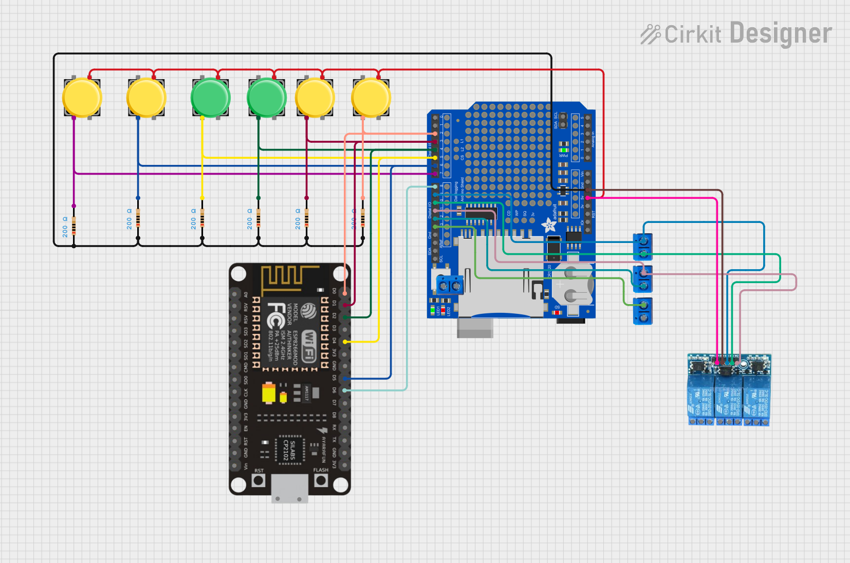
Summary
This circuit integrates an Arduino UNO with an Adafruit Datalogger Shield, multiple pushbuttons, resistors, a 3-channel 5V relay module, ESP-8266 Controller, and terminal PCBs. The Arduino UNO serves as the central processing unit, interfacing with the ESP-8266 for WiFi capabilities and controlling the relay module. The pushbuttons are used for input, and the resistors are likely for pull-up or pull-down configurations. The terminal PCBs are used for connecting external devices or sensors.
Component List
Arduino UNO
- Microcontroller board based on the ATmega328P
- It has 14 digital input/output pins, 6 analog inputs, a 16 MHz quartz crystal, a USB connection, a power jack, an ICSP header, and a reset button.
Adafruit Datalogger Shield v1
- A shield for Arduino that provides data logging capabilities.
- It includes an SD card interface and a real-time clock (RTC).
Pushbutton (6 instances)
- A simple switch mechanism for controlling some aspect of a machine or a process.
- Typically consists of four pins where two pins form a pair that is connected internally.
Resistor (6 instances, 200 Ohms each)
- A passive two-terminal electrical component that implements electrical resistance as a circuit element.
- Used for reducing current flow, adjusting signal levels, dividing voltages, bias active elements, and terminating transmission lines, among other uses.
ESP-8266 Controller
- A low-cost Wi-Fi microchip with full TCP/IP stack and microcontroller capability.
- Provides internet connectivity to the circuit.
Terminal PCB 2 Pin (4 instances)
- A simple two-pin terminal block for connecting wires to the circuit board.
3 Channel Relay 5V
- An electrically operated switch that allows you to turn on or off a circuit using voltage and/or current much higher than a microcontroller can handle.
Wiring Details
Arduino UNO
5Vconnected to the 3 Channel Relay 5VVCCGNDconnected to the 3 Channel Relay 5VGND- Digital pins
D13,D12,D11,D10,D9,D8,D7,D6,D5,D4,D3,D2are connected to various components such as terminal PCBs, relay channels, ESP-8266 Controller, pushbuttons, and resistors.
Adafruit Datalogger Shield v1
+5Vconnected to all pushbuttonsPin 3GNDconnected to all resistorspin1
Pushbuttons
- One side (
Pin 2) of each pushbutton is connected to an Arduino digital pin and a resistor. - The other side (
Pin 3) of all pushbuttons is connected to the+5Von the Adafruit Datalogger Shield.
Resistors (200 Ohms each)
- One side (
pin2) of each resistor is connected to an Arduino digital pin and a pushbutton. - The other side (
pin1) of all resistors is connected to theGNDon the Adafruit Datalogger Shield.
ESP-8266 Controller
- Various GPIO pins (
D0,D1,D2,D4,D5,D6) are connected to corresponding Arduino digital pins.
Terminal PCB 2 Pin
- Used to interface the Arduino digital pins with external devices or sensors.
3 Channel Relay 5V
VCCandGNDare powered by the Arduino5VandGND.- Relay channels
CH1,CH2,CH3are controlled by Arduino digital pinsD11,D10,D9.
Documented Code
Arduino UNO Code (sketch.ino)
void setup() {
  // put your setup code here, to run once:

}

void loop() {
  // put your main code here, to run repeatedly:

}
Note: The provided code for the Arduino UNO is a template with empty setup and loop functions. This code needs to be filled in with the logic to control the relay module, read the pushbuttons, and communicate with the ESP-8266 Controller.
ESP-8266 Controller Code
No code was provided for the ESP-8266 Controller.
End of documentation.