Arduino UNO Controlled Humidity-Responsive Fan System
Circuit Documentation
Summary of the Circuit
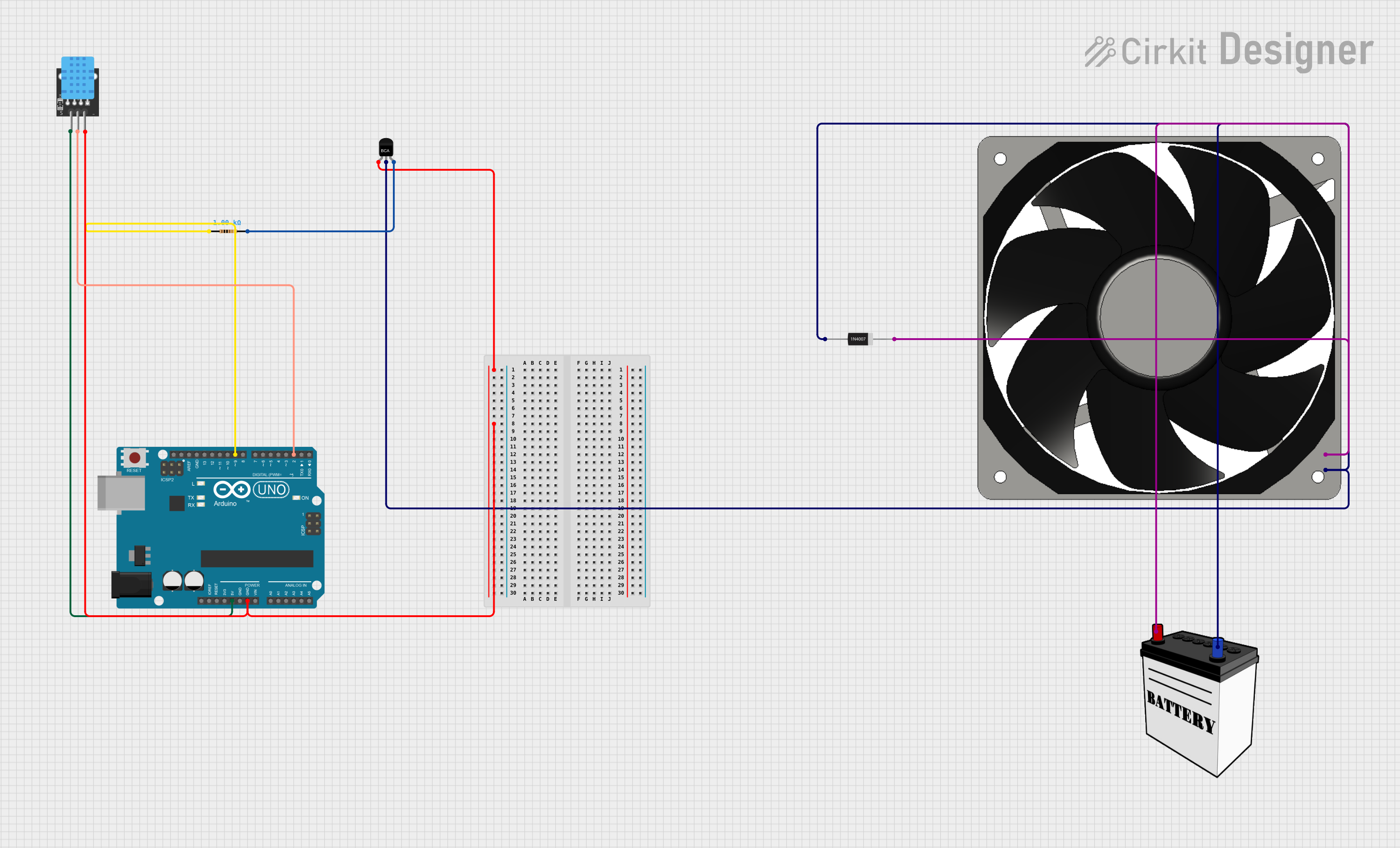
This circuit is designed to control a 12V fan using an Arduino UNO based on humidity readings from a DHT11 sensor. The fan is powered by a 12V battery and its speed is controlled through a PWM signal from the Arduino, which is interfaced with an NPN transistor acting as a switch. A resistor is used to limit the current to the base of the transistor, and a diode is included to protect against reverse voltage spikes when the fan is turned off.
Component List
Arduino UNO
- Microcontroller board based on the ATmega328P
- Provides I/O pins for interfacing with various sensors and actuators
- Includes power supply pins and a reset button
120mm Fan (12V)
- A 12V DC fan used for cooling
- Operates at 12V and requires a ground connection
NPN Transistor
- A bipolar junction transistor used as a switch to control the fan
- Has three pins: Emitter (E), Collector (C), and Base (B)
Resistor
- A 1kΩ resistor used to limit the current to the transistor's base
KY-015 DHT11 Temperature and Humidity Sensor
- A digital sensor that measures ambient temperature and humidity
- Has a data pin, power supply pin, and a ground pin
12V Battery
- Provides the power source for the fan
- Has a positive (VCC) and a negative (GND) terminal
1N4007 Rectifier Diode
- A diode used to prevent reverse voltage spikes from the fan
- Has an anode and a cathode
Wiring Details
Arduino UNO
GNDconnected to the ground of the DHT11 sensor and the emitter of the NPN transistor5Vconnected to the 5V pin of the DHT11 sensorD9connected to one end of the 1kΩ resistorD2connected to the data pin of the DHT11 sensor
120mm Fan (12V)
12V+connected to the cathode of the rectifier diode and the collector of the NPN transistorGNDconnected to the ground of the 12V battery
NPN Transistor
E(Emitter) connected to the ground of the Arduino UNOC(Collector) connected to the anode of the rectifier diode and the 12V+ pin of the fanB(Base) connected to the other end of the 1kΩ resistor
Resistor (1kΩ)
- One end connected to the D9 pin of the Arduino UNO
- The other end connected to the base of the NPN transistor
KY-015 DHT11 Sensor
5Vconnected to the 5V pin of the Arduino UNOS(Signal) connected to the D2 pin of the Arduino UNOGNDconnected to the ground of the Arduino UNO
12V Battery
VCCconnected to the cathode of the rectifier diodeGNDconnected to the anode of the rectifier diode, the ground of the fan, and the collector of the NPN transistor
1N4007 Rectifier Diode
Cathodeconnected to the VCC of the 12V battery and the 12V+ pin of the fanAnodeconnected to the collector of the NPN transistor and the ground of the 12V battery
Documented Code
#include "DHT.h"

// Pin definitions
#define DHTPIN 2      // Pin connected to the data pin of the DHT sensor
#define FANPIN 9      // PWM pin connected to the base of the transistor

// DHT sensor type
#define DHTTYPE DHT11 // Use DHT11 or DHT22, depending on the sensor

DHT dht(DHTPIN, DHTTYPE);

void setup() {
  pinMode(FANPIN, OUTPUT); // Set fanPin as an output
  dht.begin();             // Initialize the DHT sensor
  Serial.begin(9600);      // Start serial communication for debugging
}

void loop() {
  // Read humidity from the DHT sensor
  float humidity = dht.readHumidity();

  // Check if the reading is valid
  if (isnan(humidity)) {
    Serial.println("Failed to read from DHT sensor!");
    return;
  }

  // Print the humidity value for debugging
  Serial.print("Humidity: ");
  Serial.print(humidity);
  Serial.println("%");

  // Map humidity to a PWM value (0-255)
  // Assuming you want the fan to run faster at higher humidity
  int fanSpeed = map(humidity, 30, 100, 0, 255);  // Adjust 30 (min humidity) and 100 (max humidity) as needed

  // Make sure fanSpeed stays within the 0-255 range
  fanSpeed = constrain(fanSpeed, 0, 255);

  // Set the fan speed using PWM
  analogWrite(FANPIN, fanSpeed);

  // Wait before the next reading
  delay(2000);  // Read every 2 seconds
}
This code is responsible for reading the humidity level from the DHT11 sensor and controlling the speed of the fan accordingly. The humidity level is mapped to a PWM value which is then used to set the fan speed. The fan is controlled via a transistor that is driven by the PWM signal from the Arduino's D9 pin.