
Arduino UNO-Based Real-Time Clock with I2C LCD Display and Adjustable Time Buttons
View and Edit Project In Cirkit Designer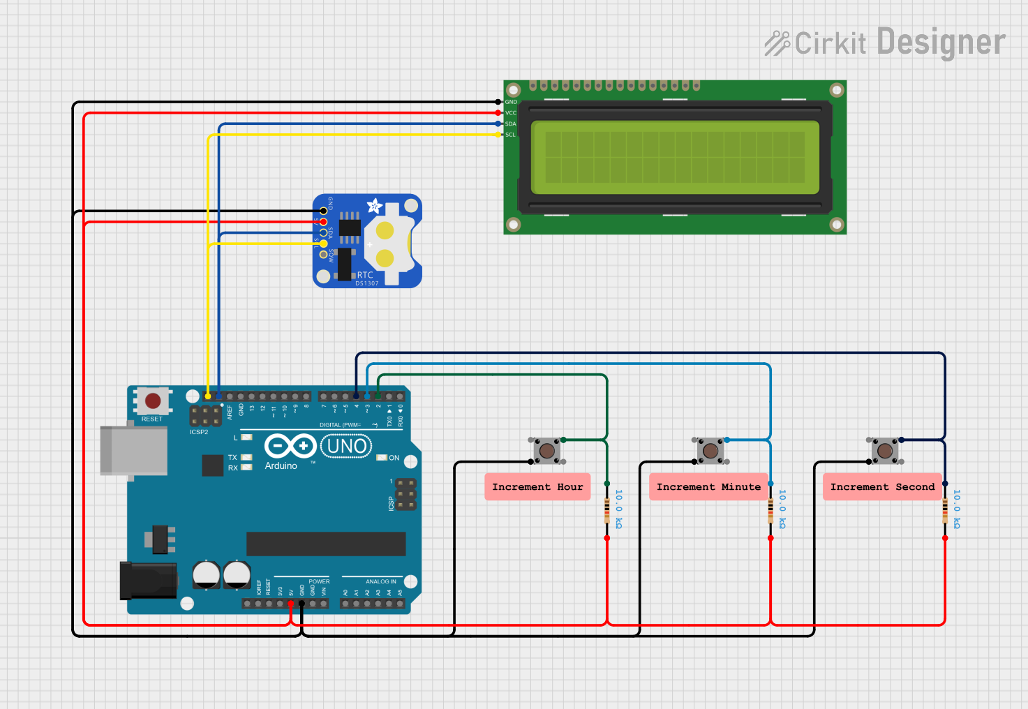
Circuit Documentation
Summary
This circuit is designed to interface an Arduino UNO with a DS1307 Real-Time Clock (RTC) module and a 16x2 I2C LCD display. It also includes three pushbuttons for adjusting the time (hours, minutes, and seconds). The circuit allows the user to view the current time on the LCD and adjust it using the pushbuttons.
Component List
Resistor
- Description: A resistor with a resistance of 10k Ohms.
- Pins: pin1, pin2
- Properties:
- Resistance: 10k Ohms
DS1307 RTC (Wokwi Compatible)
- Description: A Real-Time Clock module used for keeping track of the current time.
- Pins: GND, 5V, SDA, SCL, SQW
16x2 I2C LCD
- Description: A 16x2 character LCD display with I2C interface.
- Pins: GND, VCC, SDA, SCL
Pushbutton
- Description: A pushbutton used for user input.
- Pins: Pin 3 (out), Pin 4 (out), Pin 1 (in), Pin 2 (in)
Arduino UNO
- Description: A microcontroller board based on the ATmega328P.
- Pins: UNUSED, IOREF, Reset, 3.3V, 5V, GND, Vin, A0, A1, A2, A3, A4, A5, SCL, SDA, AREF, D13, D12, D11, D10, D9, D8, D7, D6, D5, D4, D3, D2, D1, D0
Wiring Details
Resistor
Resistor 1:
- pin1: Connected to Pin 1 (in) of Pushbutton 1 and D2 of Arduino UNO
- pin2: Connected to 5V of Arduino UNO, VCC of 16x2 I2C LCD, and 5V of DS1307 RTC
Resistor 2:
- pin1: Connected to Pin 1 (in) of Pushbutton 2 and D3 of Arduino UNO
- pin2: Connected to 5V of Arduino UNO, VCC of 16x2 I2C LCD, and 5V of DS1307 RTC
Resistor 3:
- pin1: Connected to Pin 1 (in) of Pushbutton 3 and D4 of Arduino UNO
- pin2: Connected to 5V of Arduino UNO, VCC of 16x2 I2C LCD, and 5V of DS1307 RTC
DS1307 RTC (Wokwi Compatible)
- GND: Connected to GND of Arduino UNO, GND of 16x2 I2C LCD, and Pin 4 (out) of all Pushbuttons
- 5V: Connected to 5V of Arduino UNO, VCC of 16x2 I2C LCD, and pin2 of all Resistors
- SDA: Connected to SDA of Arduino UNO and SDA of 16x2 I2C LCD
- SCL: Connected to SCL of Arduino UNO and SCL of 16x2 I2C LCD
16x2 I2C LCD
- GND: Connected to GND of Arduino UNO, GND of DS1307 RTC, and Pin 4 (out) of all Pushbuttons
- VCC: Connected to 5V of Arduino UNO, 5V of DS1307 RTC, and pin2 of all Resistors
- SDA: Connected to SDA of Arduino UNO and SDA of DS1307 RTC
- SCL: Connected to SCL of Arduino UNO and SCL of DS1307 RTC
Pushbutton
Pushbutton 1:
- Pin 1 (in): Connected to pin1 of Resistor 1 and D2 of Arduino UNO
- Pin 4 (out): Connected to GND of Arduino UNO, GND of DS1307 RTC, and GND of 16x2 I2C LCD
Pushbutton 2:
- Pin 1 (in): Connected to pin1 of Resistor 2 and D3 of Arduino UNO
- Pin 4 (out): Connected to GND of Arduino UNO, GND of DS1307 RTC, and GND of 16x2 I2C LCD
Pushbutton 3:
- Pin 1 (in): Connected to pin1 of Resistor 3 and D4 of Arduino UNO
- Pin 4 (out): Connected to GND of Arduino UNO, GND of DS1307 RTC, and GND of 16x2 I2C LCD
Arduino UNO
- D2: Connected to pin1 of Resistor 1 and Pin 1 (in) of Pushbutton 1
- D3: Connected to pin1 of Resistor 2 and Pin 1 (in) of Pushbutton 2
- D4: Connected to pin1 of Resistor 3 and Pin 1 (in) of Pushbutton 3
- 5V: Connected to pin2 of all Resistors, VCC of 16x2 I2C LCD, and 5V of DS1307 RTC
- GND: Connected to GND of DS1307 RTC, GND of 16x2 I2C LCD, and Pin 4 (out) of all Pushbuttons
- SDA: Connected to SDA of DS1307 RTC and SDA of 16x2 I2C LCD
- SCL: Connected to SCL of DS1307 RTC and SCL of 16x2 I2C LCD
Code Documentation
#include <Wire.h>
#include <RTClib.h>
#include <LiquidCrystal_I2C.h>

// Initialize the RTC and LCD
RTC_DS1307 rtc;
LiquidCrystal_I2C lcd(0x27, 16, 2); // Adjust the I2C address if necessary

const int buttonHourPin = 2; // Pin where the hour button is connected
const int buttonMinutePin = 3; // Pin where the minute button is connected
const int buttonSecondPin = 4; // Pin where the second button is connected

unsigned long previousMillis = 0; // Stores the last time the display was updated
const long interval = 1000; // Interval at which to update the display (1 second)

void setup() {
  pinMode(12, OUTPUT);
  digitalWrite(12, LOW);
  pinMode(11, OUTPUT);
  digitalWrite(11, HIGH);

  // Initialize serial communication for debugging
  Serial.begin(9600);

  // Initialize the RTC
  if (!rtc.begin()) {
    Serial.println("Couldn't find RTC");
    while (1);
  }

  if (!rtc.isrunning()) {
    Serial.println("RTC is NOT running!");
    // Uncomment the following line to set the RTC to the current date & time
    // rtc.adjust(DateTime(F(__DATE__), F(__TIME__)));
  }

  // Initialize the LCD
  lcd.init();
  lcd.backlight();
  lcd.clear();

  // Initialize the button pins as input with internal pull-up resistor
  pinMode(buttonHourPin, INPUT_PULLUP);
  pinMode(buttonMinutePin, INPUT_PULLUP);
  pinMode(buttonSecondPin, INPUT_PULLUP);
}

void loop() {
  unsigned long currentMillis = millis();

  // Check if the hour button was pressed
  if (digitalRead(buttonHourPin) == LOW) {
    // Get the current time from the RTC
    DateTime now = rtc.now();

    // Increment the hours
    DateTime newTime = DateTime(now.year(), now.month(), now.day(), now.hour() + 1, now.minute(), now.second());
    rtc.adjust(newTime);

    newTime = rtc.now();

    // Update the display immediately
    updateDisplay(newTime);

    // Debounce delay
    delay(200);
  }

  // Check if the minute button was pressed
  if (digitalRead(buttonMinutePin) == LOW) {
    // Get the current time from the RTC
    DateTime now = rtc.now();

    // Increment the minutes
    DateTime newTime = DateTime(now.year(), now.month(), now.day(), now.hour(), now.minute() + 1, now.second());
    rtc.adjust(newTime);

    newTime = rtc.now();

    // Update the display immediately
    updateDisplay(newTime);

    // Debounce delay
    delay(200);
  }

  // Check if the second button was pressed
  if (digitalRead(buttonSecondPin) == LOW) {
    // Get the current time from the RTC
    DateTime now = rtc.now();

    // Increment the seconds
    DateTime newTime = DateTime(now.year(), now.month(), now.day(), now.hour(), now.minute(), now.second() + 1);
    rtc.adjust(newTime);

    newTime = rtc.now();

    // Update the display immediately
    updateDisplay(newTime);

    // Debounce delay
    delay(200);
  }

  // Check if it's time to update the display
  if (currentMillis - previousMillis >= interval) {
    previous