
Arduino UNO Controlled Stepper Motor and Servo System with A4988 Driver and Buck Converters
View and Edit Project In Cirkit Designer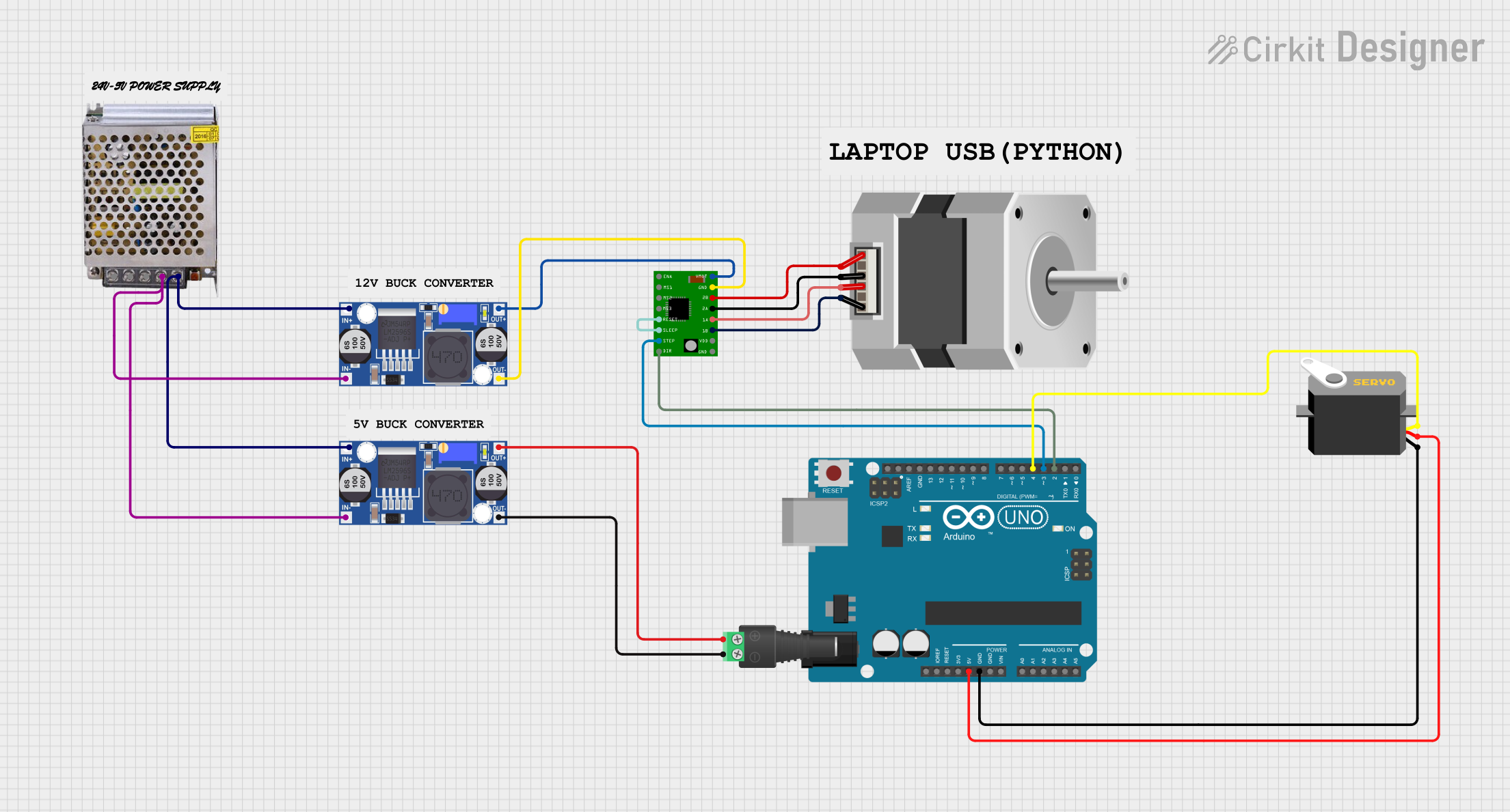
Circuit Documentation
Summary
This circuit involves an Arduino UNO microcontroller, a stepper motor driver (A4988), a bipolar stepper motor, a servo motor, and a power supply. The circuit is designed to control the stepper motor and the servo motor using the Arduino UNO. The power supply provides the necessary voltage to the components through buck converters.
Component List
A4988 Stepper Motor Driver Carrier
- Description: A driver for controlling bipolar stepper motors.
- Pins: ENABLE, MS1, MS2, MS3, RESET, SLEEP, STEP, DIR, GND, VCC, 1B, 1A, 2A, 2B, VMOT
Stepper Motor (Bipolar)
- Description: A bipolar stepper motor.
- Pins: D, B, C, A
Buck Converter
- Description: A DC-DC converter to step down voltage.
- Pins: IN+, IN-, OUT+, OUT-
POWER SUPPLY 12V 5AMP
- Description: A power supply providing 12V DC output.
- Pins: 220V Positive Pole (AC), 220V Negative Pole (AC), GND, GND (DC), 12V-24V Output (DC)
Servo
- Description: A servo motor.
- Pins: gnd, vcc, pulse
Arduino UNO
- Description: A microcontroller board based on the ATmega328P.
- Pins: UNUSED, IOREF, Reset, 3.3V, 5V, GND, Vin, A0, A1, A2, A3, A4, A5, SCL, SDA, AREF, D13, D12, D11, D10, D9, D8, D7, D6, D5, D4, D3, D2, D1, D0
2.1mm Barrel Jack with Terminal Block
- Description: A barrel jack for power connections.
- Pins: POS, NEG
Wiring Details
A4988 Stepper Motor Driver Carrier
- RESET connected to SLEEP of the same component.
- STEP connected to D3 of Arduino UNO.
- DIR connected to D2 of Arduino UNO.
- 1B connected to D of Stepper Motor.
- 1A connected to B of Stepper Motor.
- 2A connected to C of Stepper Motor.
- 2B connected to A of Stepper Motor.
- GND connected to OUT- of Buck Converter.
- VMOT connected to OUT+ of Buck Converter.
Stepper Motor (Bipolar)
- D connected to 1B of A4988 Stepper Motor Driver Carrier.
- B connected to 1A of A4988 Stepper Motor Driver Carrier.
- C connected to 2A of A4988 Stepper Motor Driver Carrier.
- A connected to 2B of A4988 Stepper Motor Driver Carrier.
Buck Converter (for A4988)
- IN+ connected to 12V-24V Output (DC) of Power Supply.
- IN- connected to GND (DC) of Power Supply.
- OUT+ connected to VMOT of A4988 Stepper Motor Driver Carrier.
- OUT- connected to GND of A4988 Stepper Motor Driver Carrier.
Buck Converter (for Barrel Jack)
- IN+ connected to 12V-24V Output (DC) of Power Supply.
- IN- connected to GND (DC) of Power Supply.
- OUT+ connected to POS of 2.1mm Barrel Jack.
- OUT- connected to NEG of 2.1mm Barrel Jack.
POWER SUPPLY 12V 5AMP
- 12V-24V Output (DC) connected to IN+ of both Buck Converters.
- GND (DC) connected to IN- of both Buck Converters.
Servo
- gnd connected to GND of Arduino UNO.
- vcc connected to 5V of Arduino UNO.
- pulse connected to D4 of Arduino UNO.
Arduino UNO
- D3 connected to STEP of A4988 Stepper Motor Driver Carrier.
- D2 connected to DIR of A4988 Stepper Motor Driver Carrier.
- GND connected to gnd of Servo.
- 5V connected to vcc of Servo.
- D4 connected to pulse of Servo.
2.1mm Barrel Jack with Terminal Block
- POS connected to OUT+ of Buck Converter.
- NEG connected to OUT- of Buck Converter.
Documented Code
Arduino UNO Code (sketch.ino)
void setup() {
  // put your setup code here, to run once:

}

void loop() {
  // put your main code here, to run repeatedly:

}
Documentation (documentation.txt)
This documentation provides a comprehensive overview of the circuit, including a summary, detailed component list, wiring details, and the code used in the Arduino UNO.