Cirkit Designer
Your all-in-one circuit design IDE
Home /
Project Documentation
Arduino UNO Ultrasonic Distance Sensor with Buzzer and LED Indicator
Circuit Documentation
Summary
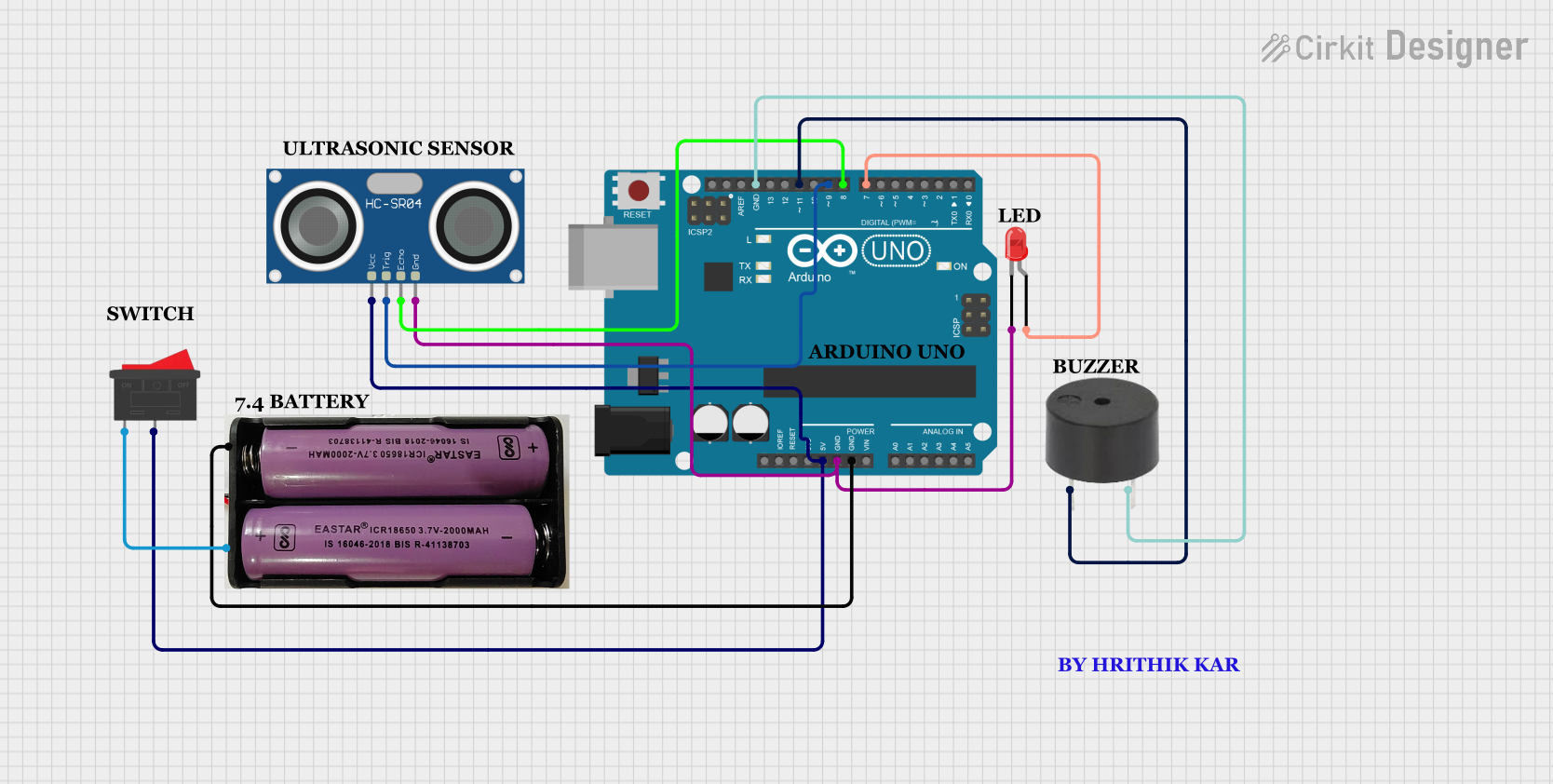
This circuit involves an Arduino UNO microcontroller interfacing with an HC-SR04 Ultrasonic Sensor, a buzzer, and an LED. The circuit is powered by a 7.4V battery through a rocker switch. The Arduino UNO controls the sensor, buzzer, and LED, and the connections are detailed below.
Component List
Arduino UNO
- Description: A microcontroller board based on the ATmega328P.
- Pins: UNUSED, IOREF, Reset, 3.3V, 5V, GND, Vin, A0, A1, A2, A3, A4, A5, SCL, SDA, AREF, D13, D12, D11, D10, D9, D8, D7, D6, D5, D4, D3, D2, D1, D0
HC-SR04 Ultrasonic Sensor
- Description: A sensor used to measure distance using ultrasonic waves.
- Pins: VCC, TRIG, ECHO, GND
7.4V Battery
- Description: A power source for the circuit.
- Pins: +, -
Rocker Switch
- Description: A switch to control the power supply from the battery.
- Pins: 1, 2
Buzzer
- Description: An audio signaling device.
- Pins: PIN, GND
LED: Two Pin (red)
- Description: A red light-emitting diode.
- Pins: cathode, anode
Wiring Details
Arduino UNO
- 5V connected to VCC of HC-SR04 Ultrasonic Sensor and 2 of Rocker Switch.
- GND connected to GND of HC-SR04 Ultrasonic Sensor, cathode of LED, - of 7.4V Battery, and GND of Buzzer.
- D11 connected to PIN of Buzzer.
- D9 connected to TRIG of HC-SR04 Ultrasonic Sensor.
- D8 connected to ECHO of HC-SR04 Ultrasonic Sensor.
- D7 connected to anode of LED.
HC-SR04 Ultrasonic Sensor
- VCC connected to 5V of Arduino UNO and 2 of Rocker Switch.
- GND connected to GND of Arduino UNO and cathode of LED.
- TRIG connected to D9 of Arduino UNO.
- ECHO connected to D8 of Arduino UNO.
7.4V Battery
- + connected to 1 of Rocker Switch.
- - connected to GND of Arduino UNO.
Rocker Switch
- 1 connected to + of 7.4V Battery.
- 2 connected to 5V of Arduino UNO and VCC of HC-SR04 Ultrasonic Sensor.
Buzzer
- PIN connected to D11 of Arduino UNO.
- GND connected to GND of Arduino UNO.
LED: Two Pin (red)
- cathode connected to GND of Arduino UNO.
- anode connected to D7 of Arduino UNO.
Documented Code
Arduino UNO Code (sketch.ino)
void setup() {
  // put your setup code here, to run once:

}

void loop() {
  // put your main code here, to run repeatedly:

}
Documentation (documentation.txt)
This documentation provides a comprehensive overview of the circuit, including a summary, detailed component list, wiring details, and the code used in the Arduino UNO microcontroller.