Arduino-Controlled Obstacle Avoidance Robot with Ultrasonic Sensor and Bluetooth Interface
Circuit Documentation
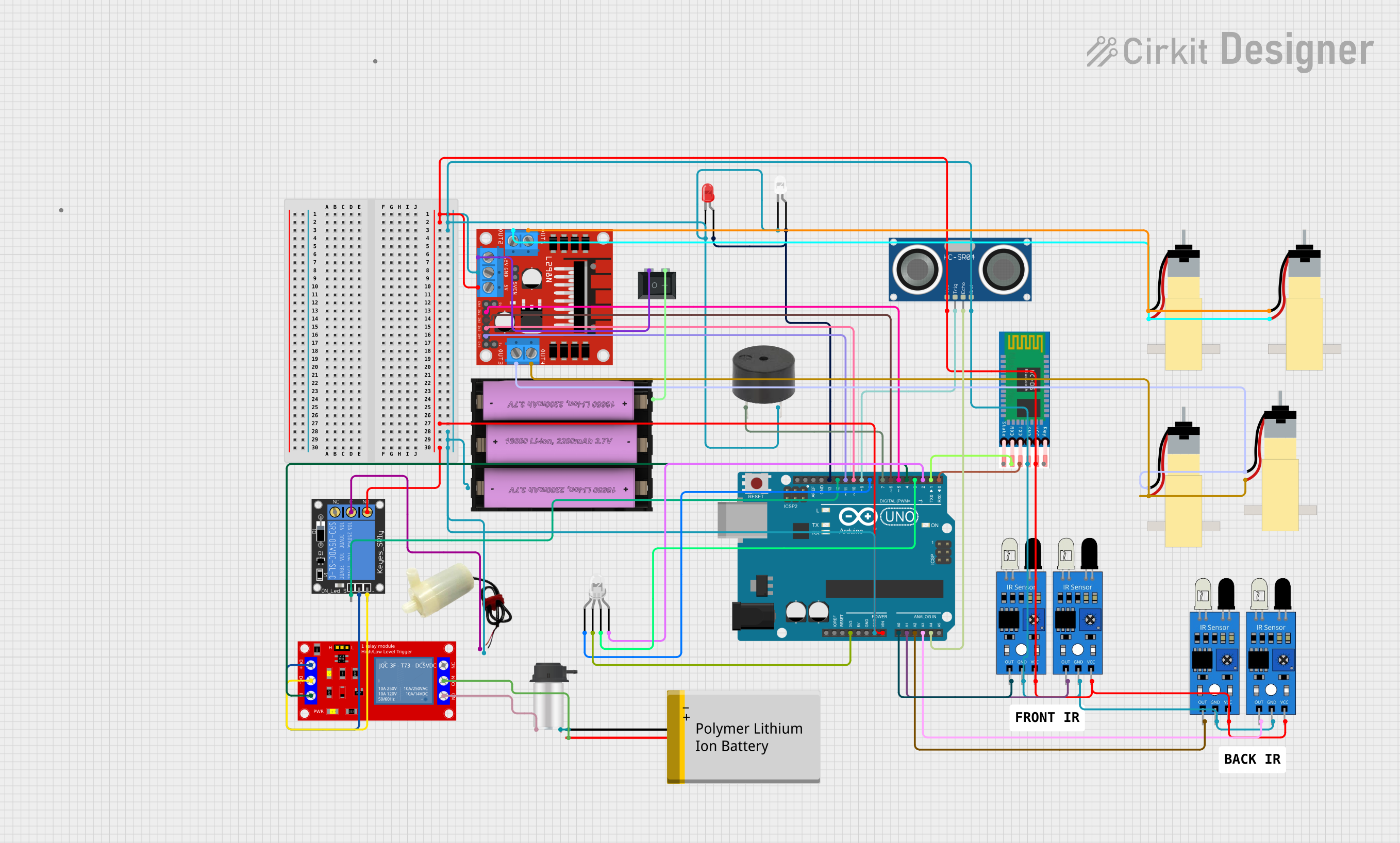
Summary of the Circuit
The circuit is designed to control a variety of components including motors, sensors, and actuators through an Arduino UNO microcontroller. It features input from ultrasonic and infrared sensors to detect obstacles, controls motors via an L298N motor driver, and includes a relay module for switching higher power loads. The circuit also has LED indicators, a buzzer for audio alerts, and a Bluetooth module (HC-05) for potential wireless communication.
Component List
1 Channel 5V Relay Module
- A relay module used for switching high power devices.
5v Mini Water Pump
- A small pump for moving water, powered by 5V.
Arduino UNO
- A microcontroller board based on the ATmega328P, used as the main controller for the circuit.
HC-SR04 Ultrasonic Sensor
- A sensor that measures distance using ultrasonic waves.
1-Channel Relay (5V 10A)
- Another relay module for controlling high current loads.
HC-05 Bluetooth Module
- A Bluetooth module for wireless communication.
LED: Two Pin (Red and White)
- Light-emitting diodes used as indicators.
L298N DC Motor Driver
- A motor driver module for controlling DC motors.
Buzzer
- An electronic buzzer for audio signaling.
Peristaltic Pump
- A type of pump used for precise fluid movement.
Polymer Lithium Ion Battery - Generic
- A rechargeable battery for power supply.
Li-ion Battery, 2200 mAh 11.1 V
- Another rechargeable battery for power supply.
Hobby Gearmotor with 48:1 Gearbox
- Motors used for driving mechanisms in the circuit.
IR Sensor
- Infrared sensors for detecting proximity or presence of objects.
Rocker Switch (SPST)
- A single pole single throw switch for controlling power.
LED: Four Pin
- A multi-color LED with separate pins for different colors.
Wiring Details
Arduino UNO
- Vin connected to various 5V supply lines.
- GND connected to various ground lines.
- 3.3V connected to the common anode of a four-pin LED.
- Digital pins (D0-D13) connected to various components for control signals.
- Analog pins (A0-A5) connected to IR sensors and the ultrasonic sensor for input signals.
L298N DC Motor Driver
- 5V and GND for logic power supply.
- IN1-IN4 for control signals from the Arduino.
- OUT1-OUT4 for motor connections.
- 12V connected to the power supply through a rocker switch.
HC-SR04 Ultrasonic Sensor
- VCC and GND for power supply.
- TRIG and ECHO connected to the Arduino for sending and receiving ultrasonic signals.
IR Sensors
- VCC and GND for power supply.
- OUT connected to the Arduino for detecting obstacles.
Relays (1-Channel Relay and 1 Channel 5V Relay Module)
- VCC and GND for power supply.
- Signal pins connected to the Arduino for control.
- NO, COM, and NC for switching external devices like the water pump and peristaltic pump.
LEDs (Two Pin and Four Pin)
- Anodes connected to power supply or Arduino pins.
- Cathodes connected to GND or Arduino pins for control.
Buzzer
- PIN connected to an Arduino pin for control.
- GND connected to the ground.
Motors (Hobby Gearmotor with 48:1 Gearbox)
- Connected to the motor driver outputs.
Rocker Switch (SPST)
- Used to control the power supply to the motor driver.
Power Sources (Batteries)
- Connected to provide power to the circuit and components.
Documented Code
#define in1 5 //L298n Motor Driver pins.
#define in2 6
#define in3 10
#define in4 11
#define EXTRA 4
const int trigPin = 9;
const int echoPin = 18;
long duration;
int distance;
#define light_FR  13    //LED Front Right   pin A0 for Arduino Uno
//#define light_FL  15   //LED Front Left    pin A1 for Arduino Uno
#define light_BR  12    //LED Back Right    pin A2 for Arduino Uno
//#define light_BL  17    //LED Back Left     pin A3 for Arduino Uno
#define horn_Buzz 7    //Horn Buzzer       pin A4 for Arduino Uno
int command; //Int to store app command state.
int Speed = 204; // 0 - 255.
int Speedsec;
int buttonState = 0;
int lastButtonState = 0;
int Turnradius = 0; //Set the radius of a turn, 0 - 255 Note:the robot will malfunction if this is higher than int Speed.
int brakeTime = 45;
int brkonoff = 1; //1 for the electronic braking system, 0 for normal.
boolean lightFront = false;
boolean lightBack = false;
boolean horn = false;
boolean extra = false;

void setup() {
  pinMode(trigPin, OUTPUT); // Sets the trigPin as an Output
  pinMode(echoPin, INPUT);
  pinMode(EXTRA,OUTPUT);
  pinMode(in1, OUTPUT);
  pinMode(in2, OUTPUT);
  pinMode(in3, OUTPUT);
  pinMode(in4, OUTPUT);
  pinMode(14,INPUT);
  pinMode(light_FR, OUTPUT);
  // pinMode(light_FL, OUTPUT);
  pinMode(light_BR, OUTPUT);
  // pinMode(light_BL, OUTPUT);
  pinMode(horn_Buzz, OUTPUT);

  Serial.begin(9600);  //Set the baud rate to your Bluetooth module.
}

void loop() {
  // Ultrasonic sensor measurement routine
  digitalWrite(trigPin, LOW);
  delayMicroseconds(2);
  digitalWrite(trigPin, HIGH);
  delayMicroseconds(10);
  digitalWrite(trigPin, LOW);
  duration = pulseIn(echoPin, HIGH);
  distance = duration * 0.034 / 2;
  Serial.println(distance);

  // Obstacle detection and buzzer alert
  if(distance < 25){
    Stop();
    delay(100);
    digitalWrite(in1,LOW);
    digitalWrite(in2,HIGH);
    digitalWrite(in3,LOW);
    digitalWrite(in4,HIGH);
    delay(500);
    Stop();
    buzzerAlert();
  }

  // IR sensor detection and buzzer alert
  if (digitalRead(14) == HIGH){
    Stop();
    delay(100);
    digitalWrite(in1,LOW);
    digitalWrite(in2,HIGH);
    digitalWrite(in3,LOW);
    digitalWrite(in4,HIGH);
    delay(300);
    Stop();
    buzzerAlert();
  }

  // Additional IR sensor routines omitted for brevity

  // Command processing from serial input
  if (Serial.available() > 0) {
    command = Serial.read();
    Stop(); //Initialize with motors stopped.
    updateLights();
    updateHorn();
    updateExtra();
    processCommand();
  }
}

// Function definitions for motor control, light updates, horn updates, etc., omitted for brevity

void buzzerAlert(){
  for(int i = 0; i < 3; i++){
    digitalWrite(horn_Buzz, HIGH);
    delay(50);
    digitalWrite(horn_Buzz, LOW);
    delay(50);
  }
}

void updateLights(){
  digitalWrite(light_FR, lightFront ? HIGH : LOW);
  digitalWrite(light_BR, lightBack ? HIGH : LOW);
}

void updateHorn(){
  digitalWrite(horn_Buzz, horn ? HIGH : LOW);
}

void updateExtra(){
  digitalWrite(EXTRA, extra ? HIGH : LOW);
}

void processCommand(){
  // Command processing logic omitted for brevity
}

// Additional function definitions omitted for brevity
This code controls the robot's movement based on ultrasonic and IR sensor inputs, processes commands received via Bluetooth, and manages the activation of lights, horn, and an extra feature. The code includes functions for moving forward, backward, turning, and stopping the motors. It also includes a braking system that can be activated electronically.