Cirkit Designer
Your all-in-one circuit design IDE
Home /
Project Documentation
Arduino UNO Temperature Monitoring System with LED Indicator
Circuit Documentation
Summary
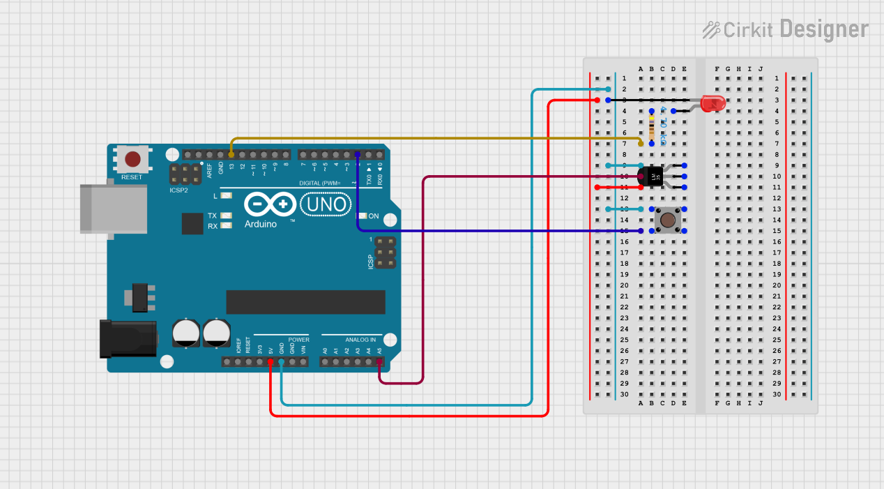
This circuit involves an Arduino UNO microcontroller, a temperature sensor (LM35), a pushbutton, a resistor, and a red LED. The circuit is designed to read temperature data from the LM35 sensor, and it includes a pushbutton for user input and an LED for visual feedback.
Component List
Arduino UNO
- Description: A microcontroller board based on the ATmega328P.
- Pins: UNUSED, IOREF, Reset, 3.3V, 5V, GND, Vin, A0, A1, A2, A3, A4, A5, SCL, SDA, AREF, D13, D12, D11, D10, D9, D8, D7, D6, D5, D4, D3, D2, D1, D0
Temperature Sensor (LM35)
- Description: A precision centigrade temperature sensor.
- Pins: +Vs, Vout, GND
Resistor
- Description: A 4700 Ohm resistor.
- Pins: pin1, pin2
- Properties:
- Resistance: 4700 Ohms
LED: Two Pin (red)
- Description: A red LED with two pins.
- Pins: cathode, anode
Pushbutton
- Description: A simple pushbutton switch.
- Pins: Pin 3 (out), Pin 4 (out), Pin 1 (in), Pin 2 (in)
Wiring Details
Arduino UNO
- D13: Connected to pin2 of the Resistor.
- GND: Connected to GND of the Temperature Sensor (LM35), cathode of the LED, and Pin 1 (in) and Pin 2 (in) of the Pushbutton.
- A5: Connected to Vout of the Temperature Sensor (LM35).
- 5V: Connected to +Vs of the Temperature Sensor (LM35).
- D2: Connected to Pin 3 (out) and Pin 4 (out) of the Pushbutton.
Temperature Sensor (LM35)
- GND: Connected to GND of the Arduino UNO.
- Vout: Connected to A5 of the Arduino UNO.
- +Vs: Connected to 5V of the Arduino UNO.
Resistor
- pin1: Connected to anode of the LED.
- pin2: Connected to D13 of the Arduino UNO.
LED: Two Pin (red)
- cathode: Connected to GND of the Arduino UNO.
- anode: Connected to pin1 of the Resistor.
Pushbutton
- Pin 1 (in): Connected to GND of the Arduino UNO.
- Pin 2 (in): Connected to GND of the Arduino UNO.
- Pin 3 (out): Connected to D2 of the Arduino UNO.
- Pin 4 (out): Connected to D2 of the Arduino UNO.
Code Documentation
Arduino UNO Code
sketch.ino
void setup() {
  // put your setup code here, to run once:

}

void loop() {
  // put your main code here, to run repeatedly:

}
documentation.txt