Cirkit Designer
Your all-in-one circuit design IDE
Home /
Project Documentation
Battery-Powered Light-Activated LED Circuit with BC547 Transistor
Circuit Documentation
Summary
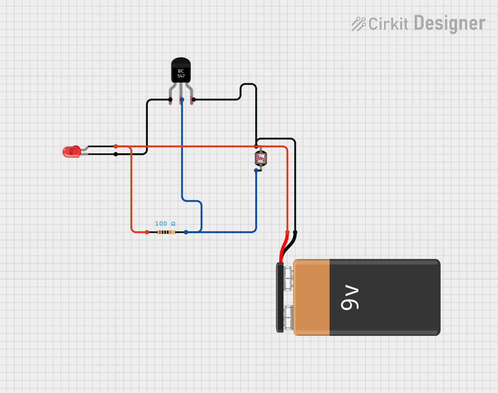
This circuit is designed to control an LED using a BC547 transistor, a photocell (LDR), a resistor, and a 9V battery. The LED will light up based on the light intensity detected by the photocell. The BC547 transistor acts as a switch, controlled by the photocell and resistor network.
Component List
BC547 Transistor
- Pins: Collector, Base, Emitter
- Description: NPN Bipolar Junction Transistor
- Purpose in Circuit: Acts as a switch to control the LED based on the input from the photocell.
Photocell (LDR)
- Pins: pin 0, pin 1
- Description: Light Dependent Resistor
- Purpose in Circuit: Senses the ambient light level and provides a variable resistance based on the light intensity.
Resistor
- Pins: pin1, pin2
- Description: Fixed Resistor
- Properties: 100 Ohms
- Purpose in Circuit: Limits the current flowing through the circuit to protect the components.
9V Battery
- Pins: -, +
- Description: Power Source
- Purpose in Circuit: Provides the necessary voltage to power the circuit.
LED: Two Pin (red)
- Pins: cathode, anode
- Description: Light Emitting Diode
- Purpose in Circuit: Emits light when current flows through it.
Wiring Details
BC547 Transistor
- Collector: Connected to the cathode of the LED.
- Base: Connected to pin 1 of the Photocell and pin 2 of the Resistor.
- Emitter: Connected to pin 0 of the Photocell and the negative terminal of the 9V Battery.
Photocell (LDR)
- pin 0: Connected to the Emitter of the BC547 Transistor and the negative terminal of the 9V Battery.
- pin 1: Connected to the Base of the BC547 Transistor and pin 2 of the Resistor.
Resistor
- pin1: Connected to the anode of the LED and the positive terminal of the 9V Battery.
- pin2: Connected to the Base of the BC547 Transistor and pin 1 of the Photocell.
9V Battery
- - (Negative): Connected to pin 0 of the Photocell and the Emitter of the BC547 Transistor.
- + (Positive): Connected to the anode of the LED and pin 1 of the Resistor.
LED: Two Pin (red)
- cathode: Connected to the Collector of the BC547 Transistor.
- anode: Connected to the positive terminal of the 9V Battery and pin 1 of the Resistor.
Code
No microcontroller code is provided for this circuit.